That circuit for TL071 should work as you have shown it, I have built it literally dozens of times like that ( I'd use 1uF but 10uF fine).
When you said it worked a bit by removing the 10 uF input cap, did you mean C1? You may have a bad cap there or reversed. It may be shorting out and messing up your bias voltage which should be 4.5Vdc across it. Your TDA circuit looks fine too.
When you said it worked a bit by removing the 10 uF input cap, did you mean C1? You may have a bad cap there or reversed. It may be shorting out and messing up your bias voltage which should be 4.5Vdc across it. Your TDA circuit looks fine too.
That circuit for TL071 should work as you have shown it, I have built it literally dozens of times like that ( I'd use 1uF but 10uF fine).
When you said it worked a bit by removing the 10 uF input cap, did you mean C1? You may have a bad cap there or reversed. It may be shorting out and messing up your bias voltage which should be 4.5Vdc across it. Your TDA circuit looks fine too.
Sorry I said the wrong cap before. If I take out the C4 (in the last schematic I posted) .22uf cap before the amp it will work sporadically. I tried swapping that for different film caps I have around like a .1uf and a 1uf but had the exact same results. Take it out and it works but it's weaker than just the amp alone.
Yes! I got chrispenycate's circuit to work. I figured out one problem was the connection at the input cap to the tl071 was bad so I fixed that. Then I was getting some sound finally but it was really a lot of screeching noise and I could barely hear my guitar over it. I kept checking everything and going over the schematic. I couldn't see anything wrong. I was experimenting a little bit though and I disconnected the gain part from the ground and that's when everything started to work. Wow, I was really blown away how clean it sounds
with chrispenycate's buffer. I got this thing hooked up to a 4" speaker and it sounds fantastic! I love how I can turn it down really low and not disturb anyone. That's why I wanted to build this and it's perfect.
Do you guys think you might know why it won't work with the C3 gain cap connected to ground?
hey, glad you got it running! There may be some connection issue around c3 to look at. There should not be huge amounts of gain, it's noticeable but you can play with the resistance ratio a bit. What is good about having a bit of gain is you could place a simple tone control after the TL071 before the power amp (if you like). Are you building this on a perfboard, or solderless breadboard?
Keep us posted, please. Generally there seems to be a lot of interest in building up guitar preamps to apply to chip amps. It's a great way to get going and have a nice lower wattage practice amp. I think most of us have the issue of not wanting to disturb anyone when musical inspiration strikes! I may start a thread on a build that I am doing, discrete preamp with possibly TDA2050. Haven't decided completely on the chip amp type yet.
Keep us posted, please. Generally there seems to be a lot of interest in building up guitar preamps to apply to chip amps. It's a great way to get going and have a nice lower wattage practice amp. I think most of us have the issue of not wanting to disturb anyone when musical inspiration strikes! I may start a thread on a build that I am doing, discrete preamp with possibly TDA2050. Haven't decided completely on the chip amp type yet.
One obvious problem is a drastic lack of supply decoupling - presumably it's running off a small 9V battery?, so you need a substantial electrolytic across the supply, and further isolation of the power amp and preamp could well be useful.
Layout could well be a concern as well - I'm hoping it's not powered like the schematic?, with the power amp fed from the preamp?.
Layout could well be a concern as well - I'm hoping it's not powered like the schematic?, with the power amp fed from the preamp?.
hey, glad you got it running! There may be some connection issue around c3 to look at. There should not be huge amounts of gain, it's noticeable but you can play with the resistance ratio a bit. What is good about having a bit of gain is you could place a simple tone control after the TL071 before the power amp (if you like). Are you building this on a perfboard, or solderless breadboard?
Keep us posted, please. Generally there seems to be a lot of interest in building up guitar preamps to apply to chip amps. It's a great way to get going and have a nice lower wattage practice amp. I think most of us have the issue of not wanting to disturb anyone when musical inspiration strikes! I may start a thread on a build that I am doing, discrete preamp with possibly TDA2050. Haven't decided completely on the chip amp type yet.
I built this one on solderless breadboard but I'm going to make another one where I'll solder it all. I'll post some pics of the completed project.
One obvious problem is a drastic lack of supply decoupling - presumably it's running off a small 9V battery?, so you need a substantial electrolytic across the supply, and further isolation of the power amp and preamp could well be useful.
Layout could well be a concern as well - I'm hoping it's not powered like the schematic?, with the power amp fed from the preamp?.
I'll add some decoupling caps. I'm not sure what you mean about the power supply. I'm still learning. The TL071 and tda2822 are both running off the same power 9v supply the way it is in the schematic. Is that bad?
I'll add some decoupling caps. I'm not sure what you mean about the power supply. I'm still learning. The TL071 and tda2822 are both running off the same power 9v supply the way it is in the schematic. Is that bad?
The power supply will go up and down as the current drawn by the power amp changes, this is fed back into the preamp causing oscillation.
So you need a substantial capacitor across the supply, and the supply feeding directly to the power amp - it's then fed to the preamp, preferably via extra decoupling components (at least a resistor and capacitor). Assuming a small 9V battery as the supply, this is particularly bad, as they have low current capability, and a high source impedance.
Will 470uf across the supply be substantial enough?
Try it and see, it's certainly a reasonable starting point.
I'm not sure what you mean though when your talking about feeding the power amp first and then into the preamp. How can I split it up like that?
Your schematic shows power coming in from the left, feeding the preamp first, then through to the power amp - that's the absolute worst way to wire it.
Wire both directly from the battery, with the preamp fed via a resistor and an extra decoupling capacitor.
Try it and see, it's certainly a reasonable starting point.
Your schematic shows power coming in from the left, feeding the preamp first, then through to the power amp - that's the absolute worst way to wire it.
Wire both directly from the battery, with the preamp fed via a resistor and an extra decoupling capacitor.
I think I understand. Here is the latest schematic hopefully with everything correct.
Attachments
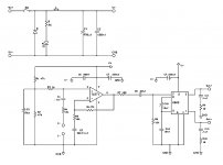
You should be very good with that. The inductor could be instead a 50 ohm resistor and still give you good decoupling. Nice touch on C5 range as that would vary the LF cutoff shelf in the range for guitar. You could be seeing oscillations from solderless breadboard..I have heard that the problem can come up. Nigel's got a good point about battery supply, this could be better on a regulated DC supply if you haven't already dine so.
I think I understand. Here is the latest schematic hopefully with everything correct.
Except that you seem to have left out the volume pot (and after the thread tile)
Except that you seem to have left out the volume pot (and after the thread tile)
I'm really debating on putting it in or not. Using the volume on my guitar seemed to work pretty good.
- Status
- This old topic is closed. If you want to reopen this topic, contact a moderator using the "Report Post" button.
- Home
- Live Sound
- Instruments and Amps
- How to add volume to TDA8541 circuit?