I'm trying to understand how dose op amp handle power supply's noise, it dosen't need to be supper correct in anyway, I just need to know roughly if power supply will be the bottle neck of a design or not. and I would like to know if my understanding of this is in anyway wrong.
Assuming using dual power to opa1642, the fluctuation of 120hz ripples will be canceled out by op amp because of op's psrr. so that shouldn't be a big problem, even the part which couldn't be canceled, will have to face op's powerful psrr.
Let's say I use LM317, after capacitor the output ripple is 200mv (assume),
lm317 with Cadj best psrr will be 75db, so the output ripple will be 35mv at 120hz? but this will be cancel out, right?
if 5mv couldn't be canceled, output noise at op's end will be,
opa1642 has +psrr at around 100db,
so output noise= 5mv*-100db* 6(op's gain),
5mv*0.00001*6=30nV
which is way too low for us to even worry about.
but what about LM317's noise,

eN will be worst 0.01%/Vo?
eN=0.0001/15v= 6uV
and combine into op amp by worst +psrr 20khz 45db,
op's noise output= 6uV*-45db(0.0056)*6(op's gain)=0.2uV
which is -131db as power supply noise floor, so i can ignore the it as well since my system isn't that good at all.
I'm thinking of put a 5 ohm resistor and 47uf capacitor as low pass to reduce high frequency noise for gain stage power supply, but if my calculation is correct, then guess I don't need it at all. i'm confused
Assuming using dual power to opa1642, the fluctuation of 120hz ripples will be canceled out by op amp because of op's psrr. so that shouldn't be a big problem, even the part which couldn't be canceled, will have to face op's powerful psrr.
Let's say I use LM317, after capacitor the output ripple is 200mv (assume),
lm317 with Cadj best psrr will be 75db, so the output ripple will be 35mv at 120hz? but this will be cancel out, right?
if 5mv couldn't be canceled, output noise at op's end will be,
opa1642 has +psrr at around 100db,
so output noise= 5mv*-100db* 6(op's gain),
5mv*0.00001*6=30nV
which is way too low for us to even worry about.
but what about LM317's noise,
eN will be worst 0.01%/Vo?
eN=0.0001/15v= 6uV
and combine into op amp by worst +psrr 20khz 45db,
op's noise output= 6uV*-45db(0.0056)*6(op's gain)=0.2uV
which is -131db as power supply noise floor, so i can ignore the it as well since my system isn't that good at all.
I'm thinking of put a 5 ohm resistor and 47uf capacitor as low pass to reduce high frequency noise for gain stage power supply, but if my calculation is correct, then guess I don't need it at all. i'm confused
Attachments
Transformer, rectifier, filter with capacitor or inductor or both, LM317, opamp.
The filter, CRC, LC, whatever, reduces the ripple before the regulator. The reg reduces it more. Forget the noise for the moment, the resistor values in the feedback network have a noise contribution, worry about that if you must.
The filter, CRC, LC, whatever, reduces the ripple before the regulator. The reg reduces it more. Forget the noise for the moment, the resistor values in the feedback network have a noise contribution, worry about that if you must.
eN will be worst 0.01%/Vo?
eN=0.0001/15v= 6uV
I don't think the units are working out there to wind up with volts in the numerator. It looks like 0.0001 per volt out. So you would need to multiply by output voltage: (0.0001)(15V) = 1.5mVrms (worst case spec, 450uVrms typical).
The datasheet for the onsemi version of the part spells that out better, below.
If you want to clean that up a bit, follow it with an LT1963A, 40uVrms from 10Hz to 100kHz.
") Just be aware the max input is 20V, so the output of the LM317 should be set at 18V or so.
Just be aware the max input is 20V, so the output of the LM317 should be set at 18V or so.http://cds.linear.com/docs/en/datasheet/1963aff.pdf(opens PDF)
I have that setup in my ODA amp's power supply
https://drive.google.com/open?id=0B67cJELZW-i8RWJ1WXRuZHdNd2s&authuser=0 (opens PDF)
works well, you just wind up with a pile of voltage regulators.
Attachments

Last edited:
I just need to know roughly if power supply will be the bottle neck of a design or not. and I would like to know if my understanding of this is in anyway wrong.
Depends if you're designing by numbers or for subjective sound quality. If the former probably your numbers aren't going to be affected much by the power supply. Subjective sound quality though is a strong function of PSU quality in my (and other listeners') experience.
Assuming using dual power to opa1642, the fluctuation of 120hz ripples will be canceled out by op amp because of op's psrr. so that shouldn't be a big problem, even the part which couldn't be canceled, will have to face op's powerful psrr.
Its true your chosen opamp has decent PSRR at LF, however at the top of the audio band its pretty poor (50dB on +ve rail).
Let's say I use LM317, after capacitor the output ripple is 200mv (assume),
lm317 with Cadj best psrr will be 75db, so the output ripple will be 35mv at 120hz? but this will be cancel out, right?
200mV taken down 75dB is 36uV. So well below the LM317's own noise output. Not an issue really.
but what about LM317's noise,
eN will be worst 0.01%/Vo?
eN=0.0001/15v= 6uV
You need to multiply by Vo, not divide. So its worst case is 100ppm of Vout which for 15V out is 1.5mV. Typically though 500uV. Note the bandwidth though is only up to 10kHz for this figure.
and combine into op amp by worst +psrr 20khz 45db,
op's noise output= 6uV*-45db(0.0056)*6(op's gain)=0.2uV
which is -131db as power supply noise floor, so i can ignore the it as well since my system isn't that good at all.
Re-do the math with the 500uV typical and 1.5mV worst case.
Then don't forget to figure in load-induced noise on the supply rails - that is the modulation of the supply noise caused by opamp output loading. Opamps don't operate in classA so take varying currents from the rails as they drive loads (both explicit and feedback networks).
I've re-do the math, it's been super helpful since I was looking for answers quite a while.
the amp i'm building now has output noise about 4.2uV at 20k hz, so the power supply's noise will integrated into signals since the op I choose has only good psrr for the LF part.
since you mention about load-induced noise, i think my 5 ohm + 47uf will cause quite a bit of unregulated voltage to power supply as trade off, but can clean up high frequency noise in cheap price. is there anyway to know if that's a good bargain or just simply a trap? because i don't know how to calculate load-induced noise
I would like to have a good noise free system for this version, see if the sound is better. last version headphone amp I built is class A IRF Current buffer with CRC supply. Well, I reduced the hum to not audible. But getting better sound I kind of need to use better, bigger capacitor, in the end the power costs much more than amp itself. With audible distortion.
That's why this time I would like to calculated a bit better
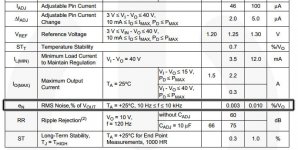
LM317 output noise at 15Vout is indeed 450uVrms typical(1.5mVrms worst case).
However that is without a cap at the adjust terminal.
Once you add that, the LM317 output noise essentialy becomes equivalent to 0.003% of the 1.25V reference voltage. So in most normal cases with say a 10-100uF cap at the adjustment terminal you would get around 1.25 x 0.00003 = 37.5uVrms typical output noise(112.5uVrms worst case). This amount of noise may vary depending on the manufacturer of the LM317 and process variations, but getting noise levels of around 50uVrms is not an issue with the LM317, even at 15Vout. Increasing the adjustment cap to 1000uF and getting noise down to the 20-30uVrms should be possible.
As an example, Douglas Self in his "Small signal audio design" book gets 39uVrms(-86dBu)noise and ripple with a simple 17Vout LM317 supply with 47uF adjustment capacitor. Although he doesn't specify the bandwidth I think is is safe to assume that he used a 20-20kHz bandwidth.
On the other hand, the LT1963A is not exactly low noise, they might state 40uVrms output noise in a 10-100kHz bandwidth but that is at 3.3Vout, at 1.5Vout they state 15uVrms output noise. It is not a 100% linear relationship between output voltage and output noise, but if we scale that up to 15Vout we are talking about (15/3.3) x 0.00004 = 181.8uVrms. Low noise? I think not.
Linearaudio did some in depth measurements of various regulators and if you look at the noise measurements you will discover that the LM317 indeed is lower noise than the LT1963A.
However that is without a cap at the adjust terminal.
Quite true - the old article by Ogiers did a good analysis
Simple Voltage Regulators Part 1: Noise - [English]
Can't really throw stones at the LM317. Even today the thing rocks, with the exception of not being low dropout like the LT chips.
On the other hand, the LT1963A is not exactly low noise, they might state 40uVrms output noise in a 10-100kHz bandwidth but that is at 3.3Vout, at 1.5Vout they state 15uVrms output noise.
Interesting thoughts. My read of the graphs on page 11 of the LT1963A datasheet and their discussion of the noise has been that the fixed voltage regulators are noisier than the adjustable. On both graphs on page 11 they show the adjustable with lower noise than any of the fixed. But.. I wouldn't be shocked if it turns out that Linear instead did those graphs at the minimum 1.21V of the adjustable regulator without stating it.
I'm going to shoot them the question tomorrow and try to get a clarification.Linearaudio did some in depth measurements of various regulators and if you look at the noise measurements you will discover that the LM317 indeed is lower noise than the LT1963A.
I'll bet that is jackinnj's analysis. If I don't have volume 4 I'm going to order it from Jan tomorrow. That article is worth having. I would tend to agree, subjectively, with his conclusion though
http://www.diyaudio.com/forums/power-supplies/229066-modern-317-337-alternatives.html#post3353689
"Noise is the least important criteria -- output impedance and PSRR seem to be more important factors in empirical evaluation of regulators. Nevertheless, listening always wins. There were regualtors which tested superbly but really screwed with the sound. "
Last edited:
Well I just heard back from a field engineer at Linear Technology. Sure enough, that plot for the LT1963A adjustable version is fact done at the minimum 1.21Vdc out, which he notes is a follower setup. That is why the adjustable version is showing lower noise than any of the fixed voltage versions since the lowest fixed voltage is 1.5Vdc. The noise gains up more of less linearly they say with increasing output voltage.
I am essentially speachless at that one, other than passing along the obvious suggestion that they add that tasty bit of information to their datasheet notes.
Turns out I didn't have volume 4 of Linear Audio and just bought it along the the current Volume 9. I see the current issue has an update on Cyril Bateman's Sound of Capacitors article from a decade ago that looks linteresting.
You can always decrease noise gain of the regulator on AC by fitting large enough capacitor into feedback loop. It works for LT1963, lm317/337 etc.
I am not quite sure about that. The LT1963A datasheet does not mention anything about it and I have never seen anyone else doing it before. However, it might be possible.
It's the same basic circuit as for the LM317, and since the part is specified for voltage output of (Vout-Vadj) up, it has to be unity-gain stable. Hence I would expect a capacitor on the ADJ pin to work - though nobody would be telling you what sort of protective measures you need. I guess a protective diode between ADJ and OUT (as already suggested for the LM317) wouldn't be a bad idea.
I hadn't thought about this option either. Seems like something worth investigating.
I hadn't thought about this option either. Seems like something worth investigating.
I am not quite sure about that. The LT1963A datasheet does not mention anything about it and I have never seen anyone else doing it before. However, it might be possible.
Believe me, it is possible
Just think, if the IC can work (remain stable) in case it is configured for an output voltage of 1.25V (or how much is there), in other words it is fine with noise gain of 1. Why it would not be stable if it has noise gain of 1 for frequencies, lets say, over 10Hz, and gain of 4 for freq lower than that? Of course you'll have to pay attention to capacitors values and ESRs, but you have to do it anyway.
It is pretty common and basic thing. DS don't have to describe it.
- Status
- This old topic is closed. If you want to reopen this topic, contact a moderator using the "Report Post" button.
- Home
- Amplifiers
- Headphone Systems
- How does op amp introduce power supply noise to output?