The purpose of my post above was simply to provide the pic. Both amps are fed the same non-inverted signal. BTW, the X1000 uses an extra box which is basicly a bunch of isolation transformers before the inputs to allow such operation. Internally the X1000 has no Earth connection except on the case which is isolated from the circuit. The downside of this whole idea is that if the amps are slightly different in terms of frequency response or in the time domain, the output will get messed up to some extent.
AudioFreak said:The purpose of my post above was simply to provide the pic. Both amps are fed the same non-inverted signal. BTW, the X1000 uses an extra box which is basicly a bunch of isolation transformers before the inputs to allow such operation. Internally the X1000 has no Earth connection except on the case which is isolated from the circuit. The downside of this whole idea is that if the amps are slightly different in terms of frequency response or in the time domain, the output will get messed up to some extent.
Thanks. As I said I had no idea how the X1000 was set up but they would need to be like that or similar to do it.
http://www.carsound.com/ubb/ultimatebb.php?ubb=get_topic;f=1;t=022066
Zapco Dave II posted;
In order to bridged two amplifiers, said amplifiers have to be single rail (dedicated mono) units. A bridging module is not necessarily needed, but it is CRITICAL that the gain structure for each amplifier is as close to identical as possible! Matching gains cannot be done by simply positioning each gain control in similar positions. There are several steps that need to be taken in order to do this correctly.
My advice would be to contact the manufacturer technical supoort folks to get the correct information for bridging two of their amps together.
We got a response;
http://www.carsound.com/ubb/ultimatebb.php?ubb=get_topic;f=1;t=022066
Originally posted by Zapco Dave II:
In order to bridged two amplifiers, said amplifiers have to be single rail (dedicated mono) units. A bridging module is not necessarily needed, but it is CRITICAL that the gain structure for each amplifier is as close to identical as possible! Matching gains cannot be done by simply positioning each gain control in similar positions. There are several steps that need to be taken in order to do this correctly.
My advice would be to contact the manufacturer technical supoort folks to get the correct information for bridging two of their amps together.
--------------------------------------------------------------------------------
Richard Clark;
not true at all---------bridging two different amps is not much different than putting a 12 volt battery in series with a 6 volt battery to obtain 18 volts............RC
more
http://www.carsound.com/ubb/ultimatebb.php?ubb=get_topic;f=1;t=001731;p=6
Richard Clark;
guys------its been so long and i have been so busy i can't even remember what has been covered and what hasn't-------at any rate i have no chance to spend much time on it now------a universal module that will work for any amp??????--------pretty difficult------or should i say rather complex in that such a versatile design would run the cost for most applications out of reason---------that is not to say that it cannot be done-------like i have stated-------ANY pair of amps can be bridged------some with better results than others-------amps are nothing more than "AC batteries" but unlike batteries they have more than 2 terminals------its the "other" terminals that can get you into trouble if you don't know what you are doing------i can easily bridge any two amps in a matter of minutes with no problem------if you have a pair that needs to be done badly enough then bring them to autosound and i guarantee that i can have any pair of amps bridged and working in 10 minutes or less or i'll pay you $1k for your trouble.................RC
thylantyr said:http://www.carsound.com/ubb/ultimatebb.php?ubb=get_topic;f=1;t=022066
Zapco Dave II posted;
In order to bridged two amplifiers, said amplifiers have to be single rail (dedicated mono) units. A bridging module is not necessarily needed, but it is CRITICAL that the gain structure for each amplifier is as close to identical as possible! Matching gains cannot be done by simply positioning each gain control in similar positions. There are several steps that need to be taken in order to do this correctly.
My advice would be to contact the manufacturer technical supoort folks to get the correct information for bridging two of their amps together.
In general when bridging PA power amps, the gain is set to max so as to match them as closely as possible and levels set with the preamps or mixers.
") ensen.
ensen.hellow guys
if u are talking about car amps then :
car battery is 12V so normal car amp will give u 12Vp-p (or 10-11Vp-p to be more accurate)
bridging two amps will give u 24Vp-p and thats it , u cant connect 2 bridged amps in series and get higher voltage (-higher power)
paralleling amps? well its possible , but why ? its better paralleling only the output transistors .
bridging 2 amps will give u higher voltage
paralleling 2 amps will give u higher current
sss said:hellow guys
if u are talking about car amps then :
car battery is 12V so normal car amp will give u 12Vp-p (or 10-11Vp-p to be more accurate)
bridging two amps will give u 24Vp-p and thats it , u cant connect 2 bridged amps in series and get higher voltage (-higher power)
paralleling amps? well its possible , but why ? its better paralleling only the output transistors .
bridging 2 amps will give u higher voltage
paralleling 2 amps will give u higher current
There are car amplifiers that run off the single +12v
battery, but there are also car amplifiers that have
high frequency switching power supplies (DC-DC converters),
12v input, +/- rail voltage output with isolated ground.
"There are car amplifiers that run off the single +12v
battery, but there are also car amplifiers that have
high frequency switching power supplies (DC-DC converters),
12v input, +/- rail voltage output with isolated ground."
99% of car amps with switching supplies out there have no more than 1KOhm isolation between speaker and 12 volt grounds. The latest trend that I notice, is to connect speaker ground directly to 12 volt ground, with a diffferential input stage to break ground loops.
Lukas
LukasLouw said:"There are car amplifiers that run off the single +12v
battery, but there are also car amplifiers that have
high frequency switching power supplies (DC-DC converters),
12v input, +/- rail voltage output with isolated ground."
99% of car amps with switching supplies out there have no more than 1KOhm isolation between speaker and 12 volt grounds. The latest trend that I notice, is to connect speaker ground directly to 12 volt ground, with a diffferential input stage to break ground loops.
Lukas
What is the reason they are connecting 12v ground
to DC-DC converter ground ?
sss said:i know there are smps car amps this is the only way u can get more power from a 12V battery (and bridging of course)
but those got nothing to do with bridging
They make smps car amplifiers with bridging capabilities.
Perhaps I don't understand the meaning of your posts?
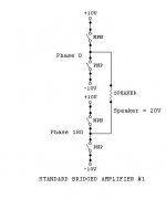
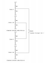
"How do you bridge two already 'bridged amplifiers'? I never seen this before.
Can someone draw a schematic or block diagram on
how this works?"
Anyone that wants to see the schematic is referred to the two-part article in Wireless World, Sept and Oct 1980.
Title: the Floating Bridge
Author: Brady
Can someone draw a schematic or block diagram on
how this works?"
Anyone that wants to see the schematic is referred to the two-part article in Wireless World, Sept and Oct 1980.
Title: the Floating Bridge
Author: Brady
thylantyr said:
They make smps car amplifiers with bridging capabilities.
Perhaps I don't understand the meaning of your posts?
The problem is not with bridging but rather with serial connection of multiple bridged amps. The amps must be floating to do this. As was stated earlier, alot of car amps are not floated.
djk said:"How do you bridge two already 'bridged amplifiers'? I never seen this before
Can someone draw a schematic or block diagram on
how this works?"
u CANT . thats what i tried to explain , it may be possible if they got separate power supply but if u are talking about car amps (without smps) that using the 12V battery then its impossible.
sss said:
u CANT . thats what i tried to explain , it may be possible if they got separate power supply but if u are talking about car amps (without smps) that using the 12V battery then its impossible.
Very very few car amps do not use a smps. Having said that, even if they use smps that is still no guarantee as stated ealier.
"What is the reason they are connecting 12v ground
to DC-DC converter ground ?"
To keep feedback from teh PSU rail voltages back to the PWM controller simple. You can in then also use an autoformer in the switching supply, which is now a little more efficient, as the primary and secondary windings "share" the primary windings.
The transformer has less copper on it, as the number of primary turns can be subtracted from the number of required secondary turns, resulting in a small cost saving. PCB layout around the primary side of the transformer is a little simpler.
You of course HAVE to use a differential input stage or something to break ground loops in a system.
Lukas
LukasLouw said:"What is the reason they are connecting 12v ground
to DC-DC converter ground ?"
To keep feedback from teh PSU rail voltages back to the PWM controller simple. You can in then also use an autoformer in the switching supply, which is now a little more efficient, as the primary and secondary windings "share" the primary windings.
The transformer has less copper on it, as the number of primary turns can be subtracted from the number of required secondary turns, resulting in a small cost saving. PCB layout around the primary side of the transformer is a little simpler.
You of course HAVE to use a differential input stage or something to break ground loops in a system.
Lukas
Is this feedback used have any
relation to whether the PSU has
a regulated output or not ? ie, if
the PSU is unregulated - do you still
need the feedback by connecting
both grounds?
- Status
- This old topic is closed. If you want to reopen this topic, contact a moderator using the "Report Post" button.
- Home
- Amplifiers
- Solid State
- How do you bridge two bridged amplifier?