No, it wont work, because the STK0100 is more than just a pair of transistors, it is the whole output stage of an amplifier. It works together with the other parts on the board to produce a whole amplifier, like this:
Q01, Q07, Q09 and associated parts form the input stage - sometimes this is referred to as a Long-Tailed Pair (LTP). It basically forms an opamp, with the left side of Q01 as the +VE input and the right side of Q01 as the -VE.
Then comes the next stage, formed by Q11,Q13,Q15,Q17,Q19 and Q21 - this is called the Voltage Amplification Stage (VAS) and this is where the signal is made larger in terms of voltage range. It is essentially the "Amplifier" part.
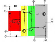
Then we have the stages contained inside the STK0010. There are two important parts - the output stage, which provides current gain, and the VBE multiplier or thermal tracking. I've attached an image showing the sections it contains.
The red part forms the VBE multiplier. The purpose of this stage is to set an "idle current" through the output stage - think similar to the idle speed on a car engine. It also tracks the temperature of the output stage to prevent thermal runaway.
The yellow part forms the predrive stage - this buffers the VAS stage which helps to lower distortion. Typically these transistors would be small high voltage transistors with a high gain, for example 2N5401/2N5551.
The green part is the driver stage, which drives the output transistors. Together with the output transistors they form a Darlington for higher gain. Typical transistors used here would be MJE15032/3.
The grey part is the output stage. These are high power transistors for carrying current. Typically these transistors should have a high power dissipation capability. There's many examples here, but I'll use On Semiconductor's MJL3281/1302 as an example.
The resistors connected to 8 and 3 are emitter resistors. These are essential to make sure slight mismatches in gain are swamped out, and also help isolate the load a little bit.
As you can see, it's quite a complex set of parts - this is why Sanyo designed these modules, it takes care of everything and eliminates having to adjust the VBE multiplier for bias when the amplifier is built. Unfortunately, the modules proved to be somewhat unreliable long term.
Q01, Q07, Q09 and associated parts form the input stage - sometimes this is referred to as a Long-Tailed Pair (LTP). It basically forms an opamp, with the left side of Q01 as the +VE input and the right side of Q01 as the -VE.
Then comes the next stage, formed by Q11,Q13,Q15,Q17,Q19 and Q21 - this is called the Voltage Amplification Stage (VAS) and this is where the signal is made larger in terms of voltage range. It is essentially the "Amplifier" part.
Then we have the stages contained inside the STK0010. There are two important parts - the output stage, which provides current gain, and the VBE multiplier or thermal tracking. I've attached an image showing the sections it contains.
The red part forms the VBE multiplier. The purpose of this stage is to set an "idle current" through the output stage - think similar to the idle speed on a car engine. It also tracks the temperature of the output stage to prevent thermal runaway.
The yellow part forms the predrive stage - this buffers the VAS stage which helps to lower distortion. Typically these transistors would be small high voltage transistors with a high gain, for example 2N5401/2N5551.
The green part is the driver stage, which drives the output transistors. Together with the output transistors they form a Darlington for higher gain. Typical transistors used here would be MJE15032/3.
The grey part is the output stage. These are high power transistors for carrying current. Typically these transistors should have a high power dissipation capability. There's many examples here, but I'll use On Semiconductor's MJL3281/1302 as an example.
The resistors connected to 8 and 3 are emitter resistors. These are essential to make sure slight mismatches in gain are swamped out, and also help isolate the load a little bit.
As you can see, it's quite a complex set of parts - this is why Sanyo designed these modules, it takes care of everything and eliminates having to adjust the VBE multiplier for bias when the amplifier is built. Unfortunately, the modules proved to be somewhat unreliable long term.
Attachments
Oh wow ...
OK I am I guess re considering the whole swap out of stk with the nearest 3 legged creature.
But what and where and how is the cross over (left channel to right channel) occurs - I suspect it has to be in the output caps ... but I dunno how to find that. Thanks.
Cool.
Srinath.
OK I am I guess re considering the whole swap out of stk with the nearest 3 legged creature.
But what and where and how is the cross over (left channel to right channel) occurs - I suspect it has to be in the output caps ... but I dunno how to find that. Thanks.
Cool.
Srinath.
OK forget it, I managed to blow the last stk ... so no stk's and no way to test this amp board. Something in it is blowing out the stk's ... I'll be using just the power supply side so I am going to get new rectifiers and caps.
I guess I am finding the input points and putting the chosen L20 or the 4046 kit amp in there.
Cool.
Srinath.
I guess I am finding the input points and putting the chosen L20 or the 4046 kit amp in there.
Cool.
Srinath.
Input stage = in the amp board right ?
I have pulled it, lots of ugly crusty looking crap. I think it needs to be tossed in the trash.
The output caps - I will make sure those are replaced I also am replacing all the input parts - the caps and the rectifier.
The DC/AC subsonic filter is useless without the main amp board, and that is betting tossed ... so I may just gut that other leg. - making it make no sound ... or like make it a pre out switch. Put it in the AC part and it will be a pre out after going through the tone controls ?
So this is now a 58v dc power supply in a pretty little chassis with a set of meters and tone controls.
So yes more stupid questions coming. But on the bright side they will be tightly focussed ... L20 specific maybe.
Cool.
Srinath.
Cool.
Srinath.
OK I am getting somewhere.
The main amp board has been removed. I have labelled everything and in fact powered the amp up without the main board in - with the ends all taped off so the thing didn't blow.
OK The DC/AC subsonic wont do anything, cos those are gone with the main board - so I am going to change it to a pre-out and main amp switch. I need to figure which is which first though.
The 60V 1/2 amp supply to that section PCB/input/opamp board is going to be left alone, the bulbs are also to be left as is. Cos I want the output meters working. Hopefully since I am hooking up the outputs of the L20 to the existing output lines will make the whole thig work without a glitch.
I need to get the 2 L20 boards in obviously after I locate the inputs after it goes through the controls.
Cool.
Srinath.

That's cool I did that once but I didn't like the looks of the chassis (had to take the plastic face plate off).
I have a L20 on the way that I'll be making a home sub out of using one of these: NE5532 LOW Pass Filter Subwoofer Process Circuit Frequency Volume FOR Amplifer | eBay
And a 10lb 40-0-40 non toroid transformer I got from a scrap metal yard.
I'm also going to make a dual stereo out of a set of L25's and L10's mounted on 2 2.6Kg heat sinks. I have what I believe is a 600VA 44-0-44 12-0-12 toroid to run the L25's.
It Should be interesting, might make a thread with pics.
David
I recently came across a dead VSX 918 pioneer.
I have a new project to re purpose this guy.
Its got a 44 - 0 - 44 ac feed out the transformer that appears to power the amp and there is 24v and some other 48 and 55 etc v ac comming out to power other things like the preamp and tuner and hdmi etc etc.
I am thinking I'll re engineer that 44 - 0 - 44 (center tapped 88 v) to power a 2 channel amp but use all the rest of the feed etc from the other parts and see if I can make it work ...
Else I guess it will be gutted and I'll just make a power amp off it.
Cool.
Srinath.
Fisher BA-6000 channel broken
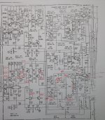
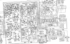
Hi, I ve received a Fisher BA-6000 which cosmetically looks very good. When it turns on the relay does not seem to click after the usual initial 2 seconds. A resistor, the R72, burned and carbonized part of the PCB below (tension of aprox 119v in between it). The power supply seems to be working ok and the VU meters move a little when the system starts.
The upper channel seems to have the right voltages, plus minus some 5% I would say. The bottom channel has problems for sure. The initial voltages seem ok for the first transistors but the farther away from input the more they vary from specs to the point we get 119v in between legs 3-8 of ICO2 when they should be zero (as if legs 2-3 and 8-9 were shorted). Does it makes any sense to try to repair this? If so any way to figure out which components are for sure wrong without a lenghty trial and error?
Can I check if the upper channel is ok by connecting a speaker before the relay or will I put at risk the speaker?
I would appreciate any help. thxs, Gus
Attachments
There is no need to connect speakers to measure the fault voltage at the output. The relay does not click because it must not connect the speakers to the amplifier when there is DC present at the output, just as designed, to protect them from the likely voltage when the module or any other conventional AB class amplifier fails. The rail voltages are nominal +/-58VDC, so you are reading the voltage across both power rails. However, the voltage of concern is from the the output terminal to speaker ground voltage, which the speakers otherwise have to cope with.
Now that hybrid audio modules are long obsolete, the replacement parts you buy will most likely be refurbs of unknown, widely varying, hand assembled quality. Were it not for the serious quality problem of using these unknown sources, you might try to resurrect the amplifier.
As it is though, removing the power amplifiers completely and retrofitting discrete amplifier modules, complete or kit form, would be a better and more dependable long-term solution.
Many thanks Ian for your comments. Effectively I had removed the shorted ICO2 and now the relay engages (although faster than the 2 seconds specified in manual).
I guess the challenge is now to either get one of those dubious $20 ICs on the internet or try a discrete solution. For the latter I have the diagram of the STK0100II, but no values of resistors or types of diodes or transistors. How do you get around this?
I by error started another post with this issue, maybe it is better to continue in the below:
http://www.diyaudio.com/forums/soli...-studio-standard-ba-6000-channel-problem.html
Many thks
Gus
- Status
- This old topic is closed. If you want to reopen this topic, contact a moderator using the "Report Post" button.
- Home
- Amplifiers
- Solid State
- How did I blow this fisher BA6000