samsagaz said:
nothing to say?
Hi,
Sorry my friend, do have any comments regarding...?
Thanks
Gareth
Hi Gareth,Technically if there are any extraneous or exposed conductive parts then these will need to be 'bonded' to earth
Tks again,
yep, i've been noticed about this before, i just think about the starground, the separated wooden box, mixed in mind about amp ground and the safety ground, thats OK, i was miss 'conductive parts'.
Well Mr Andrew,
you're answer will be the precious lesson.
Brgds.
Eka
I was surprised at your question, that's all.gareth said:-----Do remember that even if you adopt shrouded/encased terminals for all the power amp connections, as soon as you plug in a speaker lead or an input interconnect, the far end becomes the lethal risk if a mains fault has developed inside your amp. And no effective fuse rupturing mechanism if the Safety Earth is omitted.-----
Hi Andrew,
Could you please expand on what you have stated here.
Thanks
Gareth
If the mains contacts some internal part and this part comes to the outside of the insulated enclosure, then connecting a cable will take the high voltage to the other end of that cable. The risk of electrocution is now at the far end of the connected cable.
Without a Safety Earth, there is no mechanism to rupture the fuse if the mains comes into contact with internal parts. This could equally apply to a broken neutral return wire that goes astray and touches a speaker or RCA terminal.
AndrewT said:I was surprised at your question, that's all.
If the mains contacts some internal part and this part comes to the outside of the insulated enclosure, then connecting a cable will take the high voltage to the other end of that cable. The risk of electrocution is now at the far end of the connected cable.
Without a Safety Earth, there is no mechanism to rupture the fuse if the mains comes into contact with internal parts. This could equally apply to a broken neutral return wire that goes astray and touches a speaker or RCA terminal.
Hi Andrew,
No probs, generally speaking fuses are to protect from overload occurrences i.e. current imbalance between L + N. As you probably know earth is a 'back-up' in-case you lose your neutral.
Thanks
Gareth
Without a Safety Earth, there is no mechanism to rupture the fuse if the mains comes into contact with internal parts
why sud to earth?
i wonder about my fuse instalation, it might not working, the fuse only trough the main line.
maybe you can leads us hows to simply test the fuse is working?
i/o check all over the network, maybe you have the best methode?
Brgds
Eka
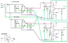
Letme show my Gnd Schematic, just need to connect the Gnd star to the Safe Earth.
Just need to use the 2 Diodes in Paralel with the Res and the cap and the are enough safe, right?
Just need to use the 2 Diodes in Paralel with the Res and the cap and the are enough safe, right?
An externally hosted image should be here but it was not working when we last tested it.
eketehe said:
why sud to earth?
i wonder about my fuse instalation, it might not working, the fuse only trough the main line.
maybe you can leads us hows to simply test the fuse is working?
i/o check all over the network, maybe you have the best methode?
Brgds
Eka
Hi Eka,
The only way you can test your fuse (without rupturing it) is to use a multi-meter set to continuity/diode test.
Put one lead at each end of the fuse and see what happens.
Thanks
Gareth
samsagaz said:Letme show my Gnd Schematic, just need to connect the Gnd star to the Safe Earth.
Just need to use the 2 Diodes in Paralel with the Res and the cap and the are enough safe, right?
An externally hosted image should be here but it was not working when we last tested it.
Hi,
Does your Gainclone have a symmetrical layout for the speaker output?
(i.e. a +/- voltage output referenced to ground).
Thanks
Gareth
Edit...you earth that comes in with the supply cable from your mains socket outlet needs to go to the 0v (centre-tap) of your transformer secondary.
gareth said:
Hi,
Does your Gainclone have a symmetrical layout for the speaker output?
(i.e. a +/- voltage output referenced to ground).
Thanks
Gareth
Edit...you earth that comes in with the supply cable from your mains socket outlet needs to go to the 0v (centre-tap) of your transformer secondary.
This is an 5 Channels amps to use with the PC. in some DIY Speakers that i made.
So the gnd needs to looks like this ?
An externally hosted image should be here but it was not working when we last tested it.
Hi There Mr Andrew , and Mr Gareth,
maybe you can answer this question :
Pls check my grounding pic too,
My personal questions are :
Hows the fuses can be ruptured?
' No probs, generally speaking fuses are to protect from overload occurrences i.e. current imbalance between L + N. As you probably know earth is a 'back-up' in-case you lose your neutral.'
is that the answer?
Hows the safety ground works, so it can save us from geting electrocuted?
In case my safety earth ground is not 'standart', hows to check that it will works well?
The exposed parts ( metal knob and panels ) and heatsink sud be connected to E or EA ? ( Pls check my pic )
They're must be some silly questions,.. i just can not continue for i have no confidence, and not intend to skip. some previous examples can not help me 'clear', maybe caused by my low IQ
Your anwers will highly appreciated .
maybe you can answer this question :
So the gnd needs to looks like this ?
Pls check my grounding pic too,
My personal questions are :
Hows the fuses can be ruptured?
' No probs, generally speaking fuses are to protect from overload occurrences i.e. current imbalance between L + N. As you probably know earth is a 'back-up' in-case you lose your neutral.'
is that the answer?
Hows the safety ground works, so it can save us from geting electrocuted?
In case my safety earth ground is not 'standart', hows to check that it will works well?
The exposed parts ( metal knob and panels ) and heatsink sud be connected to E or EA ? ( Pls check my pic )
They're must be some silly questions,.. i just can not continue for i have no confidence, and not intend to skip. some previous examples can not help me 'clear', maybe caused by my low IQ
Your anwers will highly appreciated .
Attachments
eketehe said:Hi There Mr Andrew , and Mr Gareth,
maybe you can answer this question :
Pls check my grounding pic too,
My personal questions are :
Hows the fuses can be ruptured?
' No probs, generally speaking fuses are to protect from overload occurrences i.e. current imbalance between L + N. As you probably know earth is a 'back-up' in-case you lose your neutral.'
is that the answer?
Hows the safety ground works, so it can save us from geting electrocuted?
In case my safety earth ground is not 'standart', hows to check that it will works well?
The exposed parts ( metal knob and panels ) and heatsink sud be connected to E or EA ? ( Pls check my pic )
They're must be some silly questions,.. i just can not continue for i have no confidence, and not intend to skip. some previous examples can not help me 'clear', maybe caused by my low IQ
Your anwers will highly appreciated .
Hi eketehe,
Yes as I posted before, the earth is a 'back-up' which is used under fault condition if you lose your neutral. A fuse blows when there is an electrical imbalance between live and neutral. Which is why here in the UK we put main circuit fuses in the live (phase) conductor.
With regards to exposed conductive parts (knobs and switches) then you can earth the sitch housing itself but you would find it impracticable to earth the actual knob itself, but if the shaft which the knob fits onto is metal then you would have 'continuity' to earth that way.
The casework which contains your project can be 'bonded' to your supply earth when it enters the case itself. You can then check earth continuity throughout by using your multimeter on the continuity/diode check function by connecting one probe to the earth that enters the project and putting the other prod on where you want to check.
With regards to your IQ...proper earthing techniques are daunting when you are new to this so don't worry and be patient and you will learn. Again don't worry and try to be logical.
Gareth
Edit...Eketehe, the fuses you have put in circuit near the op-amps need to be put on the secondary windings of the transformer before the bridge rectifier or you will not have complete circuit protection. This is VERY important if you do not want to kill your project.
Eketehe,
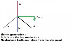
I have posted a diagram showing how electricity is generated at your power station. You will see from the diagram that earth and neutral are taken from the same point.
I hope this will clarify some points.
Gareth
Edit..sorry Eketehe but in the diagram L2 and L3 need to be swapped around so that if you read the diagram anti-clockwise it would say L1, then L2 (on the left), Neutral, L3 (on the right) and then earth and finally back to L1. Again sorry for the mistake, and I hope this helps
Attachments
eketehe said:Hi Gareth,
Dully noted, i prints your reply, for i need some time to well understand.
Tks for helpful reply, so that i may skip the experiment related, if i able to get this all clear, thats seems scary.
I'll be back,
Thks again,
Brgds.
Eka
No problems Eka, good luck!
Gareth
re post 32.
My recommendation is for a mains fuse before anything else even before the switch.
Then a mains fuse in each primary feed to the transformers.
These last pair of fuses should be close rated to just avoid nuisance blowing when the circuit is operating correctly. If any thing between these fuse and the next fuse goes faulty the primary feed fuse blows before the transformer has time to overheat.
Then fuse the supply rails, as shown in your diagram after the main smoothing caps.
For your two channel amplifier that would be 6 PCB mounted fuses and one panel mounted fuse.
AndrewT said:re post 32.
My recommendation is for a mains fuse before anything else even before the switch.
Then a mains fuse in each primary feed to the transformers.
These last pair of fuses should be close rated to just avoid nuisance blowing when the circuit is operating correctly. If any thing between these fuse and the next fuse goes faulty the primary feed fuse blows before the transformer has time to overheat.
Then fuse the supply rails, as shown in your diagram after the main smoothing caps.
For your two channel amplifier that would be 6 PCB mounted fuses and one panel mounted fuse.
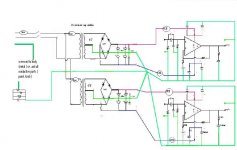
Hi There Mr Andrew,
Pls find the pic belows,
Pls kindly check if there is its OK..
( quoted )
Edit...Eketehe, the fuses you have put in circuit near the op-amps need to be put on the secondary windings of the transformer before the bridge rectifier or you will not have complete circuit protection. This is VERY important if you do not want to kill your project. ( quoted )
Hi There Mr gareth,
I'm sorry, pls kindly re-clarify above suggestion, as i find some of my amp pcb, has include the fuse terminal on board.
Pls kindly adv what is the best fuse i sud use, my friend tell me that 1,5A slowblow fuse is the matching one. is that correct ? ( 220V main, 2 x 5A E1 trafos, +/- 30VDC ) hows to count the ideal fuse amperage, so it may ruptured easily when something is going wrong?
Brgds.
Eka
- Status
- This old topic is closed. If you want to reopen this topic, contact a moderator using the "Report Post" button.
- Home
- Amplifiers
- Chip Amps
- How connect the Gnd.