Yes, I thought that even the 6" seemed a little too good to be true!
If that graph were true, there would be no need for a midrange OR a tweeter! I guess those charts are about useless for the high end- not too unusual in this business!
Here is a graph for the 12" Eminence with whizzer cone for comparison :
http://editweb.iglou.com/eminence/eminence/pages/products02/speakers/beta12lt.htm
More believable
Yes it is, the graphs are a little exagerated, too common in this world!
The 2AF is good up to 15Khz, so figure out the rest.
Speakers have very good ( the best ever heard for me ) midrange. very natural, complete, vivid, colorful!
I was thinking on using a Selenium tweeter, got into www.seleniumloudspeakers.com.br ( brazilians ) and see it.
cheers!
The 2AF is good up to 15Khz, so figure out the rest.
Speakers have very good ( the best ever heard for me ) midrange. very natural, complete, vivid, colorful!
I was thinking on using a Selenium tweeter, got into www.seleniumloudspeakers.com.br ( brazilians ) and see it.
cheers!
variovents
Hi,
Long time ago I built Dynaudio K-160 kit with a variovent. The woofer was the famous 8" W21-54 160W RMS in a 60L box. This is really one of the best woofers of that size I ever had. Dynaudio recommended two variovents per box but experiments carried out by a Dynaudio speaker and kit supplier in Australia showed that the system performed better with just one. And that is the reality - one has to experiment a little to find the best solution, which in the case of cutting wholes in speker cabinets, does not come cheaply. It pays to learn from experiments made by others.
So far I built quite a number of speker systems - mainly active. I also decided to use variovents (this time from ScanSpeak although its ieasy to make these at home) for my most recent system - still under development but already operational.
There are two practical and audible advantages of using variovents - one is well known, namely that the impedance peak goes down by at least 30% with some drop in Q and consequently all the associated goodies follow.
The other advantage of variovent is that atmospheric pressure inside and outside is always the same (like in open systems). Some people forget about it when perfectly sealing closed boxes. These should always have a tiny hole to allow for pressure equalisation - otherwise compression and expansion diaphram movements are not exactly the same with well known consequences which vary from very subtle to quite notable.
My standard approach is to build a bigger but very stiff enclosure and then fill it with enough sand to get the right volume afterwards - it saves a lot of cutting and minimizes timber waste. Too much stuffing is no good. As a matter of fact its usually better to include reflective panels (that's what I usually do with larger enclosures) covered with sound absorbing material instead. If variovents are to be used or a vent - stuffing should not exceed 30-50% and there should be a clear passage left between the woofer(s) and the (vario)vent.
That is all. Hope it may be of some use.
Cheers,
Hi all!
Will anybody be so kind to explain which woofers are best suitable for (single-chamber) variovent? Are they the same as for vented box? As for example, is Beyma 12B100-R (datasheet is here: http://www.beymapro.ru/files/manual/102.pdf )
suites well for a variovented enclosure?
Will anybody be so kind to explain which woofers are best suitable for (single-chamber) variovent? Are they the same as for vented box? As for example, is Beyma 12B100-R (datasheet is here: http://www.beymapro.ru/files/manual/102.pdf )
suites well for a variovented enclosure?
Greets!
FYI, variovents are for acoustically lowering the cab's Q at resonance, so can be used with any driver. Typically, they are used to lower the Q of a too small cab alignment (underdamped), but I primarily used DIY versions to critically damp EBS vented alignments that either required an unacceptably long vent and/or peaking at Fb.
GM
Greets!
Extended Bass Shelf........ Put a driver in an acoustically large vented cab tuned too low (preferably ~0.707*Fs) to get a low Q system above Fb. Once critically damped, in its usable passband you have the equivalent of a 0.5 Qtc sealed cab alignment except with more LF gain.
GM
Extended Bass Shelf........ Put a driver in an acoustically large vented cab tuned too low (preferably ~0.707*Fs) to get a low Q system above Fb. Once critically damped, in its usable passband you have the equivalent of a 0.5 Qtc sealed cab alignment except with more LF gain.
GM
GM said:Greets!
Extended Bass Shelf........ Put a driver in an acoustically large vented cab tuned too low (preferably ~0.707*Fs) to get a low Q system above Fb. Once critically damped, in its usable passband you have the equivalent of a 0.5 Qtc sealed cab alignment except with more LF gain.
GM
GM, thanks!
Such low port freq demands noticeable port's length. "Officially" we have "dumped tube" now, which has "S and L". This is rather different conctruction in comparison with "variovent", which has "S and dump-media thickness" Are there some benefits and drawbacks for such topological transformation?
")
Greets!
You're welcome!
True, but a too small/short vent can be damped to perform as a bigger/longer one.
'S and L'? Anyway, a thickness of damping material acoustically represents an acoustic length, so they are more like a damped ducted vent than not.
Sorry, I don't understand your question.
GM
You're welcome!
True, but a too small/short vent can be damped to perform as a bigger/longer one.
'S and L'? Anyway, a thickness of damping material acoustically represents an acoustic length, so they are more like a damped ducted vent than not.
Sorry, I don't understand your question.
GM
GM said:Greets!
You're welcome!
True, but a too small/short vent can be damped to perform as a bigger/longer one.
'S and L'? Anyway, a thickness of damping material acoustically represents an acoustic length, so they are more like a damped ducted vent than not.
Sorry, I don't understand your question.
GM
I see, my English is ugly
There are (at least) two ways to damp (not saying about a chamber damping):
- make a hole (with appropriate diameter) in an enclosure and close the hole with a damping material,
and
- make a port (tube with appropriate diameter and _length_) and fill in the tube with a damping material.
And let's imagine all cases between these ones: let's make tube length smaller (and, probably, a diameter bigger), smaller and smaller... We shell get "classical" variovent (a hole) from a vented port (a tube). So I tell about a "topological transformation".
Exactly what I have tried. For larger drivers, I have built an mdf frame, with opening about 3.5" square, and experimented from there. The aperiodic thing, when done right, will only lower the impedance peak of the driver. It gives a lower sealed box Q. It won't change the response at all. For instance, if your total box Q is .9, it might lower it to .7 or so.planet10 said:Take 2 pieces of plastic gutter mesh and sandwhich a piece of fiberglass between them. One variovent.
dave
Dave,DaveThreshold said:
Exactly what I have tried. For larger drivers, I have built an mdf frame, with opening about 3.5" square, and experimented from there. The aperiodic thing, when done right, will only lower the impedance peak of the driver. It gives a lower sealed box Q. It won't change the response at all. For instance, if your total box Q is .9, it might lower it to .7 or so.
What do you mean with "it won't change the response at all"? It's rather strange for me. If the speaker mechanical properties were changed, SPL must be changed too (I think so): a lower F3 ("more volume" like with a box filled with a fiberglass), or/and more smooth drop at low frequencies, or/and an eliminating of SPL peak (if system Q was > 0.7) or something such.
Will you be so kind to describe you experiments more in detail?
3 boxes in one
I don't have the data now, but I will try the experiment again soon in another design, and I will post the graphs of before and after.
What I do with most boxes is (if big enough) I will port it, then make my own variovent to cover the port, then I make a cap that goes over the hole, or over the port. That way I get what you could call three box designs in one.
I can see how that doesn't make sense. what I did was I put two Eton 8-480's in a 1.6 cu ft box. That was two small of a box for two of them, so I took an impedance test with LMS, then cut my ver. of a variovent in to it. The impedance peak dropped substantially, giving the impression of a bigger box. I took a response test, and it came out the same as the sealed version. I can't explain why that happens. It has worked that way on a couple different designs. I remember Madisound explaining it that way also.anli said:
Dave,
What do you mean with "it won't change the response at all"? It's rather strange for me. If the speaker mechanical properties were changed, SPL must be changed too (I think so): a lower F3 ("more volume" like with a box filled with a fiberglass), or/and more smooth drop at low frequencies, or/and an eliminating of SPL peak (if system Q was > 0.7) or something such.
Will you be so kind to describe you experiments more in detail?
I don't have the data now, but I will try the experiment again soon in another design, and I will post the graphs of before and after.
What I do with most boxes is (if big enough) I will port it, then make my own variovent to cover the port, then I make a cap that goes over the hole, or over the port. That way I get what you could call three box designs in one.
O.K Anli here it is. I dug it out and re-tested today.
The box: An old fisher xp-7 box which I rebraced, re-baffled and tightened up a lot. By the time I was done, I decided it would have been better and easier to just build new ones. It is 1.6 cubic ft. net. - after the drivers, bracing etc. It is also packed with egg crate mattress pad foam. There is a hole cut in the back of the box for a 3" cardboard tube vent. I reinforced the rear wall, so when left bare, the hole is 1-3/8 deep by 3-3/16 wide. (I wish the U.S. would convert to the metric system). Over this the aperiodic frame is placed when in use. The frame is much wider than the vent hole, to be used in other applications.
The drivers: 2-Eton 8-480-32 hex. They are wired in parallel, and acousticaly they are not separated inside the box. In other words wile the box is in sealed mode, if you push on one, the other will move out. IMO this is almost the perfect situation to use an aperiodic. Both drivers in this box are simply two much for it. They need at least 1cu. ft. each when sealed. Between the loads of stuffing, and the aper. vent, I was trying to make this box as "effectively large" as i could.
The testing: L.M.S. by Linearx was used. On all graphs it was set for the max of 800 data points, and set between 10hz to 1khz, to get as much resolution on the low end as possible.
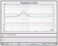
[See next post for Z graphs]
On the z graphs, you can see that the frequency of the impedance peaks are almost the same, but not quite. The aper. graph has a peak about 2hz higher than the sealed graph. Obviously the Z peak is reduced about 6 ohms with the aper. vent in use. That may not seem like much, but keep in mind the box is stuffed more than your average turkey, so when sealed the Z peak will be about as low as you can get it. Notice on the left side of the aper. graph, it runs about 1/2 ohm higher than the sealed box, all the way down to 10HZ.
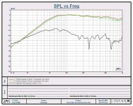
On the S.P.L. graphs, you can see that they are very close, but there is something going on that I can't explain: The left part of the aper. graph runs about 1db lower than the sealed graph. I hope other people here, can take a stab at explaining that one. I've tried a few aperiodic enclosures, and this happens every time. Can it be as simple as phase cancellation by the aper. vent? The black graph is the aperiodic vent, close miked, at the exact same distance as the woofer (about3/8".)
The box: An old fisher xp-7 box which I rebraced, re-baffled and tightened up a lot. By the time I was done, I decided it would have been better and easier to just build new ones. It is 1.6 cubic ft. net. - after the drivers, bracing etc. It is also packed with egg crate mattress pad foam. There is a hole cut in the back of the box for a 3" cardboard tube vent. I reinforced the rear wall, so when left bare, the hole is 1-3/8 deep by 3-3/16 wide. (I wish the U.S. would convert to the metric system). Over this the aperiodic frame is placed when in use. The frame is much wider than the vent hole, to be used in other applications.
The drivers: 2-Eton 8-480-32 hex. They are wired in parallel, and acousticaly they are not separated inside the box. In other words wile the box is in sealed mode, if you push on one, the other will move out. IMO this is almost the perfect situation to use an aperiodic. Both drivers in this box are simply two much for it. They need at least 1cu. ft. each when sealed. Between the loads of stuffing, and the aper. vent, I was trying to make this box as "effectively large" as i could.
The testing: L.M.S. by Linearx was used. On all graphs it was set for the max of 800 data points, and set between 10hz to 1khz, to get as much resolution on the low end as possible.
[See next post for Z graphs]
On the z graphs, you can see that the frequency of the impedance peaks are almost the same, but not quite. The aper. graph has a peak about 2hz higher than the sealed graph. Obviously the Z peak is reduced about 6 ohms with the aper. vent in use. That may not seem like much, but keep in mind the box is stuffed more than your average turkey, so when sealed the Z peak will be about as low as you can get it. Notice on the left side of the aper. graph, it runs about 1/2 ohm higher than the sealed box, all the way down to 10HZ.
On the S.P.L. graphs, you can see that they are very close, but there is something going on that I can't explain: The left part of the aper. graph runs about 1db lower than the sealed graph. I hope other people here, can take a stab at explaining that one. I've tried a few aperiodic enclosures, and this happens every time. Can it be as simple as phase cancellation by the aper. vent? The black graph is the aperiodic vent, close miked, at the exact same distance as the woofer (about3/8".)
Attachments
Dave,
Thanks a lot for your long report about your experiments! I have a food to think now
My humble English prevents me to understand all. Can you clarify some details?
- how do drivers located against each other? As I can understand (one is ON while the other is OFF), at this case internal volume is constant, and variovent influence must be reduced very significantly,
- have not understood "the hole is 1-3/8 deep by 3-3/16 wide". Does it mean something like "1 _and_ 3/8 inches" ans "3 _and_ 3/16 inches"?
request for dynaudio asymetric isobaric speaker enclosure designs
Dear fellow Audio builders,
Being inspired by SY 's Quote of
" Dynaudio also used them (variovents) as resistive structures in the interior of asymmetric isobaric enclosures. One of the best speakers I ever built used a 30W54 on the outside, 21W54 on the inside at right angles to the 30W, with the 21W firing through a Variovent. Astonishingly clean bass."
I am inspired to try to build a pair of these. Have the drivers and the variovents. Am seeking box dimensions and any construction tips.
Any and all help welcome and appreciated.
Thanks
Alopa
- Status
- This old topic is closed. If you want to reopen this topic, contact a moderator using the "Report Post" button.
- Home
- Loudspeakers
- Multi-Way
- How about the sealed box with "variovent"?