Better yet, 20 to 80 hertz since we are talking SUBwoofer. The lowest note on a 88 key piano is 27.5hz.IF you size and construct your horn correctly what you loose in a horn is operational bandwidth. An optimal horn will get you about two octaves at peak efficiency. So, say 32 to 128 hertz. or 40 to 160 hertz. You can massage a horn to trade some efficiency for bandwidth. As for sound, I have compared horns with open baffle. What can be concluded is that the much smaller excursion requirements that a horn allows are most beneficial in terms of lowering the distortion, and increasing the possible transient response.
If a speaker movers, then it distorts.
Speakers move less in a bandpass enclosure than IB, OB, BR, or Sealed enclosures per a given voltage.
Bandpass = BP4, BP6, FLH, TH, ROAR, Paraflex, or any buried driver enclosure.
Yeah that's what I've heard. I can't flip the rear chamber as that is the only way the huge, 50kg 18" sub will fit.I would not have the rear port firing into the front port with this design. It's kinda defeating the BP6S principle. I'd move the front port to the red square or flop the rear chamber. The driver should fire into the front port. See the example pic.
But what should I use in Hornresp as the front chamber length, if I put the port on the red square or perhaps in the middle of the front baffle?
The front chamber length changes the response massively, more than most changes to the rear chamber, so I should get it right.
I'm going to start with the baffle thickness, 27mm, but I will probably add some more length to it, at least a protruding round over.The length of your front port is the thickness of the wood. I use 1.905cm for 0.75in wood.
I have a 3D printer, would a round or 'racetrack' -shaped port be noticeably better?
This is kind of an end game build, so I'd like to get the most out of it, both SPL and SQ wise.
My goal right now is to get as much output as possible, from the space I have available in the trunk, for as wide of a bandwidth as feasable.For a "musical" BP trunk install, I would have a rising response to the low pass filter frequency at 2pi. The response should be flat at 0.5pi. You will loose midbass response with a flat 2pi BP enclosure. See the Devastator responses on avsforum.com. Those 2pi BP6P designs are PERFECT for car audio.
My 12" mids have a 50-60Hz HPF and they play pretty well that low with 400W each, so I'd like to get the sub to play up to 80-100Hz to cross over well.
This subwoofer has about a 50mm thick top plate, 90mm long coil, 40-45mm of one-way xmax and 50mm xmech.
So it's made to play the lows, but of course I'd like it to play the midbass area as well if it can.
But the driver baffle is set in place in the trunk and the front chamber baffle cannot extend past the rear seats, so I have a set amount of space for the rear and front chambers, including their ports.
AFAIK the only way to get a rising response from this setup would be to have a bigger front chamber, but that is unfortunately not possible right now.
Also, I want a rising response down to 20Hz in the car, as motor and road noise get louder at lower frequencies, so for a flat 'sounding' response I'd want a considerable bass boost at 20Hz.
Here's my current L and R response:
The drop after 10kHz is caused by the horns' response, but this sound pretty flat when driving and playing close to full tilt. Only that the 20-25Hz range was missing.
How much better? Can I make the port smaller if it's round/rounder?Yes, rounder ports are better than square ports.
The bottom is around 30cm deep and top is around 12cm deep, so 21cm is the average depth.According to this pic, the front chamber length is 21.
Is 21 at the base or middle of the slanted board?
In that case my first model (the gray line) was the correct one, but wouldn't the subwoofer placement parameter LO1 be incorrect then, as it cannot be far enough in the simulation?
But does this mean that the depth is always 21cm in this instance, regardless of rear and front port placement?
Define smaller. A circle will have a larger diameter than a square of the same volume, but the square will probably have a a bigger diagonal measurement.How much better? Can I make the port smaller if it's round/rounder?
Why a circle is better (not just the opening) is that for any given area, the circle will have less air drag than any other shape. This is because the circumference is smaller than any other shape of the same volume. Also from the centre to the edge is longer, meaning less wall interaction.
Sometimes you can get away with a smaller circle because it flows better, but there would obviously be caveats attached.
While it might have less distortion due to more efficient / less driver movement, that doesn't take into consideration sound quality and trying to pass the sound through some kind of ports.Better yet, 20 to 80 hertz since we are talking SUBwoofer. The lowest note on a 88 key piano is 27.5hz.
If a speaker movers, then it distorts.
Speakers move less in a bandpass enclosure than IB, OB, BR, or Sealed enclosures per a given voltage.
Bandpass = BP4, BP6, FLH, TH, ROAR, Paraflex, or any buried driver enclosure.
Probably 25 years ago I had a crack at building a 6th order isobaric band pass box out of 32mm MDF. Granted while I thought I had the ports right I probably didn't, it just sounded like a muffled boomy mess. So much so that the cabinet is now the base for my pedestal drill.
The front chamber depth is 21cm no matter the port placement.How much better? Can I make the port smaller if it's round/rounder?
The bottom is around 30cm deep and top is around 12cm deep, so 21cm is the average depth.
In that case my first model (the gray line) was the correct one, but wouldn't the subwoofer placement parameter LO1 be incorrect then, as it cannot be far enough in the simulation?
But does this mean that the depth is always 21cm in this instance, regardless of rear and front port placement?
I am attempt to reverse understand (not quite reverse engineer) the wizard. I am trying to double check results I got from using and designing a Bass Box Pro 6 Bass Reflex cabinet.
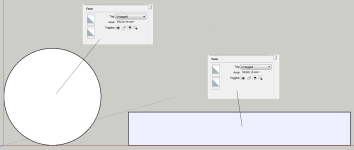
So I used the wizard to create a half space (2.0?), Direct Radiator, Bass Reflex, Normal which gives this result, but when I go back to the Input Parameters
I ASSUME that the S1 - S5 boxes wouldn't ordinarily be 0.00, so there really isn't a way to learn what these figures should really be to create this shape using the wizard. I tried modelling something that looks like shape in the picture but the end of the port is blocked off if you try and put something in S1 and S2, so I see there are three possible scenarios that can explain it.
1. It is a picture for reference only and is unachievable.
2. The only way it can be achieved is by reversing what is in the picture
3. Something else
Does anyone know how if what is in the picture can actually be modeled? and if so what that might look like in the top boxes?
Also how do you tell it where the driver is going? TIA.
Being colourblind I think there is a red line there on the right hand side of the picture to indicate the driver. Is that red or am I seeing things?
I made a mistake. You have to use 1 segment and length with Ap1 and Lp to create a BR enclosure, unless it's a HR version 50.70 issue. I cannot update my work laptop to the current version due to IT security.
Here are 4 models of the same 2ft3 BR enclosure (12" high x 12" wide x 24" long) with a 24" long port.
I used HR's default speaker parameters as the driver.
I'm guessing the 50.70 version of HR is the reason for the volume variance between the Stepped model (66.073 liters) and the other 3 models (66.069 liters).
Yeah I meant can I get away with a smaller area round port, compared to a square port?A circle will have a larger diameter than a square of the same volume, but the square will probably have a a bigger diagonal measurement.
E.g. would I get the same performance with a round port with 80% of the area of the square port?
Or where does the line go?
Because my 3D printer can only print 32x32cm, which is 1024cm^2, just barely over the 1000cm^2 I simulated, which tbh. was an arbitrary number, close to Sd.
Also, how should I calculate port corner length compared to straight length?
How about these parts?:
Ahh yes I have yet to make the mental association with those values, and didn't see them there. I just went back a few pages to see what David said about each of those values / explanations. Using the Rosetta Stone I can now try and see what you have done in the examples.HR is versatile enough to model a BR enclosure with either....
Segments and lengths,
Vrc, Lrc, Ap, & Lpt,
Or
Ap1, Lp, Vtc, & Atc.
Vrc specifies the rear chamber volume in litres.
Lrc specifies the rear chamber length in centimetres.
Fr specifies the airflow resistivity of any acoustical material lining the rear chamber in mks rayls/m.
Tal specifies the thickness of the acoustical lining material in centimetres.
Vtc specifies the volume of the throat chamber in cubic centimetres.
Atc specifies the cross-sectional area of the throat chamber in square centimetres (when used, Atc is often set equal to Sd).
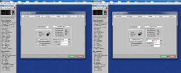
Theoretically you should be able to... I use BassBox 6 Pro because I have been unsuccessful to date to model something in Hornresp (I've given up but still trying to understand it) and unfortunately it can't model very sophisticated boxes in BBP6 which is a pity. But this is a driver that I am trying to model at the moment in a bass reflex cabinet.
On the port page I have selected no port flares to remove any influence from the result. And I pressed calculate the minimum port to achieve xmax. In Sketchup I made two shapes the exact size the BBP6 is recommending to make sure they are the same (they are pretty close) but notice the length difference between them. This illustrates that even though they are the same area they require a different length purely because of air friction.
Now what concerns me is that these two figures seem back to front. The round port with its lower air resistance should be longer than the rectangle to compensate for it lack of drag, but I suspect this is some poorly written code (there is so much poor quality code out there it blows my mind).
But regardless if it is right or wrong it illustrates that port shape is going to have a bearing on length / diameter (you SHOULD be able to go to a smaller diameter and keep the same port length as a rectangle). In terms of port shape a rectangle is far worse than a square or a circle. If you were doing a simple bass reflex like I am trying to do I would say go with a circle to avoid port chuffing, but your port design is far more complex than a simple tube I would say stay with as close to a square as you can get.
The trade off between round and square is not huge. Compared to the hassle to create round ports in your design. Just to satisfy my own curiosity I will try and model a square port and see what I come up with.
Attachments
Using SketchUp again and checking the area I got the area to very close at 232.7mm (using the xmax button it corrected it to 232.8 at 1630 the same as the circle), but this clearly demonstrates that the BBP6 port section can't be trusted as it says that a square is pretty much the same as a circle, but a rectangle is different. I'd like to say I am surprised, but I'm not.

Vrc specifies the rear chamber volume in litres.
Lrc specifies the rear chamber length in centimetres.
Fr specifies the airflow resistivity of any acoustical material lining the rear chamber in mks rayls/m.
Tal specifies the thickness of the acoustical lining material in centimetres.
Vtc specifies the volume of the throat chamber in cubic centimetres.
Atc specifies the cross-sectional area of the throat chamber in square centimetres (when used, Atc is often set equal to Sd).
Oh goodie, my Fr has just turned into a Ap, now what does that mean... Ap Direct radiator vented-box enclosure port cross-sectional area (sq cms) Helmholtz resonance frequency = 58.4 hertz
Just put that into Gooogle translate for people that speak English... hmmm port cross sectional area.. OK so that is just a complicated way of saying the area of the port... So now because there isn't an area calculator in the software (at least not where it would be obvious and useful) it looks like I am going to have to do some math to work out how big of a port I am asking for to get this number since we tend to think of ports in dimensions not area.
Being lazy just going to ask Gemini that is likely to get it wrong anyway... 7.96cm circle diameter. OK can now visualise that.
If I have a Vrc of 27.5 litres why do I now need a Lrc? All I need is a volume, unless it plans to use the Lrc to scale the drawing...Anyway letting that go and moving on.
Lpt... OK what is that? I don't have that in my list. Lpt Direct radiator vented-box enclosure port tube length (cm) Port tube air mass = 0.60 gm End connection = 2.45cms.
Let's break this down... OK yes we are going to need a length to work out the volume of the port, since we already have the surface area. That makes sense. We then have a weight of the air in that volume, yep that makes sense too. End connection.... Get out the translator again... Logic would suggest that is the size where it connects to the box?, or maybe the opening of the port? but the port diameter is 7.96cms where did this 2.45cms number come from???
OK brain is stuck again. Push forward please.
To model the main (first) enclosure resonance.why do I now need a Lrc?
Length of portLpt... OK what is that?
")
I suppose that means end correction?End connection = 2.45cms
At the port exits there is some "outside" air coupled to the air in the port. That added mass adds a virtual increase of port length.
- Home
- Loudspeakers
- Subwoofers
- Hornresp