So I am guessing then a chamber only becomes a chamber when it is physically isolated from the other parts of the cabinet.
In the default Hornresp design the sealed rear chamber is located behind the driver and could be considered to be physically separated, but the throat chamber is positioned between the front side of the driver diaphragm and the horn throat, and so in this case is not really physically isolated.
Without wishing to complicate the issue it is perhaps worth noting that Hornresp can model a chamber component taking resonances into account, or alternatively, as a pure acoustic compliance. When modelled as a compliance any resonances that the chamber would normally produce are masked.
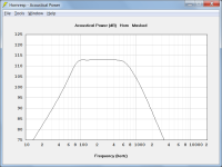
Attachment 1 shows the default record with the chambers modeled as pure compliances. Any chamber resonances are masked.
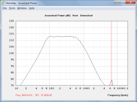
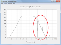
Attachment 2 shows the default record with chamber resonances taken into account. Notice the resonance spike at around 6600 Hz due to the presence of the throat chamber. (The throat chamber axial length is approximately half a wavelength at 6600 Hz).
Attachments
Double click on the graphs to show every 3 dB's.
Just to clarify, double-clicking on the chart itself activates the Sample tool. It is necessary to double-click in the vicinity of the chart Y-axis labels to change the dB scale.
Switching from the default 5 dB to 3 dB or 6 dB scale increments actually makes very little difference to the overall chart resolution. With 5 dB increments the chart range is 50 dB and with 3 dB or 6 dB increments it improves only slightly to 48 dB.
Sometimes I am trying to tickle a few db between designs and it can be rather difficult to show people that there is actually a difference between the two.
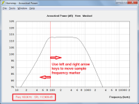
The Sample tool can be used to reveal small variations in response as the frequency changes, as shown in Attachment 1.
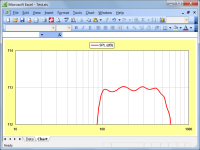
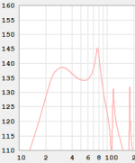
Alternatively, the chart data can be exported and plotted with an appropriate range in Excel or similar, as shown in Attachment 2.
Attachments
Attachment 2 shows the default record with chamber resonances taken into account. Notice the resonance spike at around 6600 Hz due to the presence of the throat chamber.
Further to the above, no rear chamber resonances are shown because they are damped out by lining material specified in the default record using the Fr and Tal parameters. If the lining material is removed however the rear chamber resonances become obvious, as shown in the attachment.
Attachments
Thanks David. I have never used the sample tool. Now I will be!The Sample tool can be used to reveal small variations in response as the frequency changes, as shown in Attachment 1.
Alternatively, the chart data can be exported and plotted with an appropriate range in Excel or similar, as shown in Attachment 2.
In the case of an offset driver transmission line design, a rear chamber is not required, which is why Vrc, Lrc, Fr and Tal are set to zero. The design in the video makes no allowance for a throat chamber which is why Vtc and Atc are also set to zero.
You also said...
In the default Hornresp design the sealed rear chamber is located behind the driver and could be considered to be physically separated, but the throat chamber is positioned between the front side of the driver diaphragm and the horn throat, and so in this case is not really physically isolated.
I am a little confused here... In the video when he offset the driver I thought he had created a chamber "behind" the driver. But then you said "a rear chamber is not required", then you said that a chamber doesn't necessarily have to be isolated to be considered a chamber, so now I am unsure if when he moved the driver further along the path he created a rear chamber or not.
And if he has in fact created a chamber why it didn't need a value putting in the lower boxes.
In the video when he offset the driver I thought he had created a chamber "behind" the driver. But then you said "a rear chamber is not required", then you said that a chamber doesn't necessarily have to be isolated to be considered a chamber, so now I am unsure if when he moved the driver further along the path he created a rear chamber or not.
I can understand why it might seem a little confusing
") .
.The closed-throat first horn segment can certainly be considered to be a chamber if you wish.
It is necessary however for Hornresp to use a horn segment component rather than the rear chamber component because it is simply not possible for the rear chamber to be specified in the position required in the offset design. It can only be located on the rear side of the driver.
Hopefully the attach screenprints will make things a bit clearer.
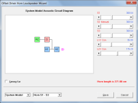
Attachment 1 shows the system model for the offset design shown in the video.
You can consider segment H1 to be a chamber if you wish.
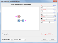
Attachment 2 shows the system model for the offset design shown in the video but with the rear chamber component included.
Notice how there is now only one sound output from the system, not two.
Attachments
I am reluctant to say I get it, but I sort of get it... There are times when a chamber is a chamber and is factored into the output, and there are other times when it looks like a chamber but it is really part of something else. Horns confuse the crap out of me. Think I am going to stick with building a simple BR enclosure for these drivers and I can do that in BBP6.
The offset driver option creates a chamber "behind" the entry point of the driver, but it's still at the front side of the diaphragm, so it's not a rear chamber. When talking about front and rear chambers, that's in relation to the driver diaphragm, where you consider the side with the magnet to be the rear side.I am a little confused here... In the video when he offset the driver I thought he had created a chamber "behind" the driver. But then you said "a rear chamber is not required", then you said that a chamber doesn't necessarily have to be isolated to be considered a chamber, so now I am unsure if when he moved the driver further along the path he created a rear chamber or not.
In it's simplest form, a tapped horn requires 7 boards just like a bass reflex enclosure. The difference is the TH has lower distortion and more output per a given voltage. TH = BP6S.
How does it compare musically? Currently I have two (one each side) 18" drivers in open baffle configuration without baffles. This obviously does nothing for SPL but delivers fantastic sound quality. My concern about any type of horn is affecting the sound quality too much by adding colour through the box. With BR at least the driver is in free air.
I should also mention that I am thinking of changing my current three way open baffle into a 4 way. I am thinking of replacing the 18" with four 6.5" in a U baffle and using the 18" to provide only sub 80Hz.
Last edited:
The offset driver option creates a chamber "behind" the entry point of the driver, but it's still at the front side of the diaphragm, so it's not a rear chamber. When talking about front and rear chambers, that's in relation to the driver diaphragm, where you consider the side with the magnet to be the rear side.
Yeah that was the bit I was struggling with. It is both sides of the back of the driver, but at the same time 100% behind the rear of the diaphragm. So when talking chambers it is more about what is in front or behind the diaphragm that seems to determine if it is a chamber or not, more than if it is a sealed cavity or not.
So why is it that the frequency response changed when he moved the driver? Was this due to creating two different length paths?
IF you size and construct your horn correctly what you loose in a horn is operational bandwidth. An optimal horn will get you about two octaves at peak efficiency. So, say 32 to 128 hertz. or 40 to 160 hertz. You can massage a horn to trade some efficiency for bandwidth. As for sound, I have compared horns with open baffle. What can be concluded is that the much smaller excursion requirements that a horn allows are most beneficial in terms of lowering the distortion, and increasing the possible transient response.How does it compare musically? Currently I have two (one each side) 18" drivers in open baffle configuration without baffles. This obviously does nothing for SPL but delivers fantastic sound quality. My concern about any type of horn is affecting the sound quality too much by adding colour through the box. With BR at least the driver is in free air.
I should also mention that I am thinking of changing my current three way open baffle into a 4 way. I am thinking of replacing the 18" with four 6.5" in a U baffle and using the 18" to provide only sub 80Hz.
What can be concluded is that the much smaller excursion requirements that a horn allows are most beneficial in terms of lowering the distortion, and increasing the possible transient response.
Doesn't matter what I do I can't get my driver diaphragm to move more than about 1mm - 2mm playing very loudly. I know this is out of the ordinary for open baffle but I think it has something to do with it being a pro driver. While it doesn't move much what is there is excellent.
Well since I only really need between 20Hz and say 80-100Hz where the four 6.5" would take over bandwidth could be traded for optimized efficiency.
Hi, can someone help me model this more accurately?
It's a series tuned 6th order enclosure, shown without the top and rear panels and front port length.
It's in a trunk so that's why the odd shape and size constrains.


Here is how I've modeled it in Hornresp, but I'm not sure how the model would change if I move the front port to the right side instead.
As this is my initial design but I was told It'll play better with the rear port loading off the front wall instead of going straight to the front port.
But as the front chamber is so thin and wide, if I change the front port location to the other side, is that the same as changing the Lc1 (chamber length) to the width (110cm in red) instead of the front enclosure depth (21cm average in gray):


Because if this is the case, I'd have to drastically change my design because the tuning drops from 25 to 19Hz and I lose out on a lot of SPL.
And if I just try to make the rear port shorter, it will make the rear chamber bigger and the tuning won't change that much, I just lose out on port loading more.
It's a series tuned 6th order enclosure, shown without the top and rear panels and front port length.
It's in a trunk so that's why the odd shape and size constrains.
Here is how I've modeled it in Hornresp, but I'm not sure how the model would change if I move the front port to the right side instead.
As this is my initial design but I was told It'll play better with the rear port loading off the front wall instead of going straight to the front port.
But as the front chamber is so thin and wide, if I change the front port location to the other side, is that the same as changing the Lc1 (chamber length) to the width (110cm in red) instead of the front enclosure depth (21cm average in gray):
Because if this is the case, I'd have to drastically change my design because the tuning drops from 25 to 19Hz and I lose out on a lot of SPL.
And if I just try to make the rear port shorter, it will make the rear chamber bigger and the tuning won't change that much, I just lose out on port loading more.
take into consideration the cabin gain, the response will change drastically!It's in a trunk
https://www.diyaudio.com/community/threads/cabin-gain-in-a-ford-explorer.56719/
Yeah, I know it will.take into consideration the cabin gain, the response will change drastically!
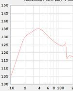
Here's a measurement of a 15" in the same external enclosure, just with 200l rear chamber and 100cm long 24cm diameter port, no front chamber:
So I know relatively well how it changes because the front chamber port will be around the same place as the port mouth was in this picture.
It's very hard to simulate cabin gain in Hornresp AFAIK, so I just look at the relative responses between enclosures.
E.g. here's the simulation of the 6th order with the 18" and the measured ported enclosure with the 18":
So I just see that I will get a lot more output in the 20-90Hz range with the 6th order, and that is the point of this build, SPL and bandwidth.
Plus the 6th order should/could play better in the car as both the rear port and cone are coupled to the front port and exit as one source into the cabin, so less phase issues.
And I have a Helix dps.2 to take out that nasty peak at 80hz.
Attachments
Last edited:
I would not have the rear port firing into the front port with this design. It's kinda defeating the BP6S principle. I'd move the front port to the red square or flop the rear chamber. The driver should fire into the front port. See the example pic.


The length of your front port is the thickness of the wood. I use 1.905cm for 0.75in wood.

The length of your front port is the thickness of the wood. I use 1.905cm for 0.75in wood.
For a "musical" BP trunk install, I would have a rising response to the low pass filter frequency at 2pi. The response should be flat at 0.5pi. You will loose midbass response with a flat 2pi BP enclosure. See the Devastator responses on avsforum.com. Those 2pi BP6P designs are PERFECT for car audio.
- Home
- Loudspeakers
- Subwoofers
- Hornresp