So does Hornresp simulate the effects of stuffing in a reflex enclosure? Or could it? Can it? Just asking. That would be rather useful. When you simulate more realistic enclosure shapes as it is now possible to do, you do get to see internal effects, and the resulting changes in the impedance and phase. I have used this for a few clients to show how an enclosure is not a black box, but a part of the entire system. Being able to simulate the differences is a very powerful tool.When you say the "Q losses feature" I assume that you are referring to QL, the vented-box enclosure quality factor parameter. If so, then it only applies to bass-reflex type systems. TH and PH system losses can be allowed for by specifying absorbent filling material.
Mark
Is this something that Hornresp can do?
No.
So does Hornresp simulate the effects of stuffing in a reflex enclosure?
Absorbent filling material can be added if the bass reflex loudspeaker is specified using two stepped segments, with the length of segment 2 increased to include the internal end correction.
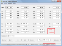
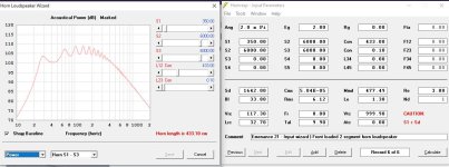
Attachment 1 shows the input parameter values for a standard bass reflex loudspeaker design. The length of the port tube internal end correction is 5.19 cm.
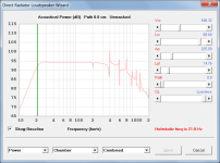
Attachment 2 shows the response of the bass reflex loudspeaker with resonances not masked and QL set to lossless.
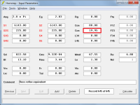
Attachment 3 shows the bass reflex equivalent design specified using two stepped segments with port tube length L23 = Lpt + EC = 14.76 + 5.19 = 19.95 cm
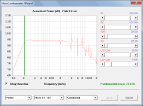
Attachment 4 shows the response of the two-segment equivalent design. It is identical to that of the bass-reflex system. Absorbent filling material can be added to the segment 1 chamber and/or segment 2 port tube as required.
Attachments
Thanks for the answer. Still learning how to use it.....
Very interesting. My lack of Knowledge of electrical Transformers allows me to have no prejudice of what a "transformer" should be.... this look has kept me focused on the idea of efficiency and impedance which is more complex than it seems at face value. For example, I would theorize that it is the lack of acoustical resistance at lower frequency, that reduces the transfer of energy. Then you have to turn and look at the Acoustical Resistance of the driver or Resonator as being High in comparison to air... and becoming lower with increased radiation mass size. What throws me off is that there is actually more resistance with increased VV due to radiation mass area, but its obviously not called acoustical resistance. Loading of the Diaphragm, it is resistance, is what I mean to say. A mechanical Resistance I presume.The analogy of the horn as a transformer can be easy to misunderstand, as an electrical transformer is a single, relatively wide-band component. But a horn transform impedance over distance, and the transformation is dependent on the wavelength compared to the distance traveled, and the rate of expansion per wavelength. So the transformation ratio is frequency dependent, and you also get other effects you won't see in an electrical transformer, like time delay and reflections from the mouth.
In the simplest model of the electrical transformer, voltage is transformed by the turns ratio and current by the inverse of the turns ratio. So a 10:1 transformer steps voltage down by a factor of 10, and current is stepped up by a factor of 10. It is done in one step, and is wideband and has relatively little parasitic effects. A horn needs distance (in terms of wavelengths) to transform impedance.
Yes, impedance is more complex than it first looks. In particular since there is both resistance and reactance, where resistance is the part that dissipates power (either useful or losses) and reactance stores energy. Mechanical reactance is typical masses and springs, that store energy by inertia or compression. Impedanse-wise, a mass is analogous to an inductor. Starting with Newton's F = ma, and given that acceleration is 2*pi*frequency*velocity, and mechanical impedance is force/velocity, we get Z = m * 2*pi*f, which is equivalent to the impedance of an inductor, Z = L * 2*pi*f.
As for efficiency, it can be useful to look at the speaker as a voltage divider between the impedances in the driver and the radiation impedance. When the diaphragm moves, it pushes against the air, and this force, divided by the diaphragm velocity, is the radiation impedance. There is a resistance part, which comes from useful radiation (and it falls away at low frequencies), and a reactive part, which comes from the air circulating back and forth near the diaphragm. The smaller the diaphragm, the higher the corner frequency of the radiation resistance, and therefore the lower the radiation efficiency at lower frequencies.
Usually the low efficiency of a loudspeaker is both due to the resistive losses (primarily the voice coil resistance and Rms) and the moving mass. Moving the mass back and forth shunts energy away from the radiation. And it's primarily due to the mass that the impedance of the driver is much higher than that of the air.
Acoustical and mechanical impedance are closely linked, since acoustical impedance is pressure/volume velocity, pressure is force/area and volume velocity is velocity * area. So mechanical impedance = acoustical impedance * area^2.
Just look for electrical, acoustical and mechanical lumped equivalent analogies.Very interesting. My lack of Knowledge of electrical Transformers allows me to have no prejudice of what a "transformer" should be.... this look has kept me focused on the idea of efficiency and impedance which is more complex than it seems at face value. For example, I would theorize that it is the lack of acoustical resistance at lower frequency, that reduces the transfer of energy. Then you have to turn and look at the Acoustical Resistance of the driver or Resonator as being High in comparison to air... and becoming lower with increased radiation mass size. What throws me off is that there is actually more resistance with increased VV due to radiation mass area, but its obviously not called acoustical resistance. Loading of the Diaphragm, it is resistance, is what I mean to say. A mechanical Resistance I presume.
There are many easy to read articles written about this.
I think especially the comparison tables will make you understand these things a bit better
")
Low efficiency mostly just has to do with this. All others are bare significant.And it's primarily due to the mass that the impedance of the driver is much higher than that of the air.
Severe mismatch in acoustical impedance.
Very similar to a mismatch in impedance of any electrical transmission line.
Putting 100W of electrical power in, getting barely 1W of acoustical power out. The rest is wasted.
The main reason why horns are way more efficient, since they are much better in coupling these impedances together.
There are online virtual machines that can run from any browser.I have an old version of HR since our company security will not allow us to download ANYTHING (internet or flash drives) to our laptops.
You don't need to download anything for that, you also don't need any privileges.
There are some free Linux ones (maybe limited time?), or just run one from home and you're good to go
Hornresp runs with Wine just fine, or you can use some old Windows version or so.
Why is the dB not going up at 52.54hz from 4S x 4P to 8S x 8P with the same 2K watts?
Your question is in essence similar to the one asked by camplo in Post #14,056, and as for that post, it would require a lot of work to identify the specific reason why the results you have observed are what they are.
I am confident however, that the multiple speaker model calculations are correct, and the simple sanity check below confirms this.
For a fixed speaker input voltage, doubling the number of speakers increases the bass output by 6 dB. (3 dB due to having twice as many speakers plus 3 dB due to having improved acoustical loading conditions)
Doubling the number of speakers a second time improves the bass by another 6 dB, meaning that going from 4S x 4P (16 speakers) to 8S x 8P (64 speakers) with no change in speaker input voltage, increases the bass output by a total of 12 dB.
Hornresp assumes however that a single signal source feeds the speaker array, so that for a constant Eg, the voltage across each speaker in the 8S x 8P array will be half that of each speaker in the 4S x 4P array. This means that instead of the difference between the 4S x 4P and 8S x 8P arrays being 12 dB in total, it is reduced by 6 dB, making a final difference of 6 dB.
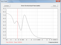
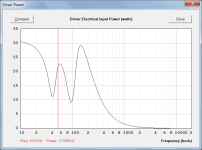
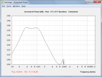
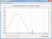
For your 4S x 4P array the output at 10 Hz is 105 dB (see attachment 1) and for the 8S x 8P array it is 111 dB (see attachment 2), a 6 dB difference, as predicted above.
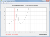
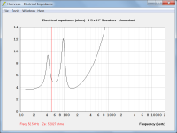
As far as input powers to the two arrays are concerned, they are not "the same 2K watts". The input power would only be 2 kW if the load was a purely resistive constant 3.6 ohms (Re). See attachments 3 and 4 for the actual load magnitudes.
The total input power to the 4S x 4P speaker array is 21.5993 watts x 4 drivers x 16 speakers = 1.38 kW at 52.54 Hz. See attachment 5.
The total input power to the 8S x 8P speaker array is 5.0326 watts x 4 drivers x 64 speakers = 1.29 kW at 52.54 Hz. See attachment 6.
Attachments
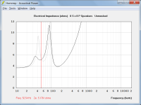
Basically, the ohm load is not the same with 8S x 8P compared to 4S × 4P at 52.54hz.
The speaker array electrical input impedances are certainly different overall, but are quite close at 52.54 Hz, as shown in the attached comparison. The grey trace applies to the 4S x 4P array and the black trace applies to the 8S x 8P array.
The results at 52.54 Hz shown below have been manually calculated to further confirm that the Hornresp multiple driver and multiple speaker simulation models are working correctly.
4S x 4P Speaker Array:
Frequency = 52.54 Hz
Array Electrical Input Impedance = 5.2027 ohms
Driver Electrical Input Power = 21.5993 W
Power Conversion Efficiency = 29.7200 %
Driver Acoustical Output Power = 6.4193 W
Speaker Acoustical Output Power = 25.6772 W
Array Acoustical Output Power = 410.8360 W
Half Space Radiation Surface Area = 6.2832 m^2
Output Pressure = 164.6331 Pa
SPL = 138.3098 dB
8S x 8P Speaker Array:
Frequency = 52.54 Hz
Array Electrical Input Impedance = 5.1761 ohms
Driver Electrical Input Power = 5.0326 W
Power Conversion Efficiency = 23.9202 %
Driver Acoustical Output Power = 1.2038 W
Speaker Acoustical Output Power = 4.8152 W
Array Acoustical Output Power = 308.1748 W
Half Space Radiation Surface Area = 6.2832 m^2
Output Pressure = 142.5875 Pa
SPL = 137.0610 dB
Attachments
Hi David, I've run into a weird problem. I'm trying to sim the effect of adding a restriction in a TL that's located between the closed section of the line and the driver. I thought using the "OD2" option in Hornresp, but it keeps jumping to some sort of Ripole thing when I do that. Is there something I'm doing wrong?


hi gang,
this is a sub bass sub, made to hug a wall. it is very simply but large, therefore it reaches low ( 25hz ) and is pretty loud. come to think of it I should have used 1/4 space instead of 1/2 space sim.. whoops. easy fix
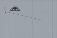
since the start of the horn ( CSA ) is 6.12cm x 57.15cm = 349.758^2cm = S1, the entry to the horn looks more like a slot to the 21" drive unit. the little throat I am talking about becomes more apparent in the attached drawing. the driver is side loaded ( or maybe in this case top loaded? ) into the horn throat as early as possible. is the simulator asking me to make the horn throat as skinny as the bottom of the horn? in other words should I be letterboxing the driver entry to 6.12cm where the diaphragm injects into the top?
anyone more advanced than me, feel free to judge and give input on potential improvements
thanks
this is a sub bass sub, made to hug a wall. it is very simply but large, therefore it reaches low ( 25hz ) and is pretty loud. come to think of it I should have used 1/4 space instead of 1/2 space sim.. whoops. easy fix
since the start of the horn ( CSA ) is 6.12cm x 57.15cm = 349.758^2cm = S1, the entry to the horn looks more like a slot to the 21" drive unit. the little throat I am talking about becomes more apparent in the attached drawing. the driver is side loaded ( or maybe in this case top loaded? ) into the horn throat as early as possible. is the simulator asking me to make the horn throat as skinny as the bottom of the horn? in other words should I be letterboxing the driver entry to 6.12cm where the diaphragm injects into the top?
anyone more advanced than me, feel free to judge and give input on potential improvements
thanks
Attachments
Last edited:
I'm trying to sim the effect of adding a restriction in a TL that's located between the closed section of the line and the driver. I thought using the "OD2" option in Hornresp, but it keeps jumping to some sort of Ripole thing when I do that. Is there something I'm doing wrong?
Hi Brian,
You are not doing anything wrong, the OD2 offset driver option does indeed specify a Ripole folded open baffle type loudspeaker. The best that you can do is to use the OD1 option to position the driver at S3, as you have already done.
What I don't understand is why in your OD2 Input Parameters window screenprint 'OD1 Single driver' is displayed in the status bar panel at the bottom of the window when it should show 'OD2 Single driver'. Also, I don't know why a run-time error should be generated after switching from OD1 to OD2. I experience no such problems. I assume you are using the latest release of Hornresp?
Kind regards,
David
give input on potential improvements
The following offset driver horn design using parabolic segments is probably closer to the system shown in your drawing.
Hi David, I'm not sure why the program crashed at that point. Seemed to work perfectly fine afterwards.Hi Brian,
You are not doing anything wrong, the OD2 offset driver option does indeed specify a Ripole folded open baffle type loudspeaker. The best that you can do is to use the OD1 option to position the driver at S3, as you have already done.
What I don't understand is why in your OD2 Input Parameters window screenprint 'OD1 Single driver' is displayed in the status bar panel at the bottom of the window when it should show 'OD2 Single driver'. Also, I don't know why a run-time error should be generated after switching from OD1 to OD2. I experience no such problems. I assume you are using the latest release of Hornresp?
View attachment 1250042
Kind regards,
David
This is what I'm trying to accomplish. Using the "OD1" option unfortunately would put the driver at S3 not S4. What I'm trying to figure out is if placing a restriction in the line before the driver could be used to filter out a particular resonance frequency. I thought "OD2" puts the driver at S4, but that doesn't seem to be the case.
- Home
- Loudspeakers
- Subwoofers
- Hornresp