We would need a rule for that also, to account for different taper ratiosOh, I forgot, that 0.341 is a bit of a ratch and only applies to straight TLs. It quickly reduces to 0.33 once the TL is tapered.
") .
.I think this information from Martin's paper can be used to determine the required taper ratio to achieve a particular Fb, given L (step 3 in the process I gave above).

Basically, work out SF, using SF= L*4*Fb/c (where c = speed of sound)
Then use the table to determine the nearest taper ratio that matches the required SF.
Even better would be to do a curve fit for the table above, and then use the corresponding equation to work out TF for any SF.
Basically, work out SF, using SF= L*4*Fb/c (where c = speed of sound)
Then use the table to determine the nearest taper ratio that matches the required SF.
Even better would be to do a curve fit for the table above, and then use the corresponding equation to work out TF for any SF.
That equation is for the DESIRED Fb, not the actual Fb of a TL.If your equation Fb = (Vas / Vb) ^ 0.31 * Fs applies, then for a given Vas and Fs, Fb won't change if Vb is kept constant
For a TL, actual Fb will change if Vb is kept constant, but the TL's length is shortened and the taper rate is changed.
What needs to be done here is to determine the taper ratio required for a particular path length in order for the TL to achieve the DESIRED Fb.
I ran a few curve-fit attempts using Martin's tables and I don't like the results that much.
I think we'll need to just generate a few Hornresp sims, track how Fb changes with length and taper ratio (with Vb held constant), then use that to come up with an equation that allows us to compute one from the other. I'll have a look at that when I have some time...
I think we'll need to just generate a few Hornresp sims, track how Fb changes with length and taper ratio (with Vb held constant), then use that to come up with an equation that allows us to compute one from the other. I'll have a look at that when I have some time...
QL=15 assumes REALLY low losses.This is consistent with Martin's comment: "The older alignment tables tended to produce a very large enclosure compared to a bass reflex design", and is the reason why he decided to change his method.
I gathered from Martin's comment: "Also using the LDC BR alignment tables a lot more potential geometries are available that produce different enclosure volumes by accounting for different alignments (BB4, SC4, and QB3) as well as different amounts of box losses QL", that the user would need to select the most appropriate Vance Dickason table for a given design. In further email correspondence, Martin has clarified that for a transmission line system only the QL = 15 tables really need to be considered, so in the next update I will add the QL15/QB3/SQB3 (chart 2.6) and QL15/SC4/C4 (chart 2.9) alignments as options. The existing alignment in Method MK 2021 is QL15/SBB4/BB4 (chart 2.3).
If Hornresp does not take losses into consideration when doing an OD alignment, it might be the best fit.
I think the "optimum box" equation I provided assumes a QL of 7
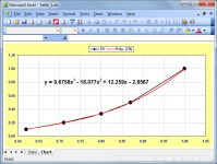
I did that for just the tapered data when I first read Martin's 2021 paper, and came up with the following:Even better would be to do a curve fit for the table above, and then use the corresponding equation to work out TF for any SF.
TR = 9.6758 * SF ^ 3 - 18.077 * SF ^ 2 + 12.259 * SF - 2.8567
Attachments
Last edited:
Thanks for the clarification, I think I now understand the problem. The tricky part will be finding a solution...For a TL, actual Fb will change if Vb is kept constant, but the TL's length is shortened and the taper rate is changed.
What needs to be done here is to determine the taper ratio required for a particular path length in order for the TL to achieve the DESIRED Fb.
.Ooh, this thing is busting my brain...
Here's the issue - finding the length of a pipe of given volume that will resonate at frequency F is not all that easy, and that's basically required for these equations to work properly.
Consider the case of a straight pipe closed at one end
L*S=Vb,
where
L =length
S = cross-sectional area
The resonant frequency is not given by the equation
F= n*v/(4*L)
but by the equation
F= n*v/(4*(L+0.4*D))
where
F = resonant frequency
n = integer, (1..3..5.. etc)
v = speed of sound (m/s)
L = length of pipe
D = diameter of pipe
From that equation, we get
L+0.4*D = n*v/(4*F)
The equivalent diameter of the pipe is given by
D=2*(Vb/(L*PI))^0.5
So, the equation works out to be
L+0.8*(Vb/(L*PI))^0.5 = n*v/(4*F)
...and we need to solve for L, LOL.
ugh.
Of course we can always ignore the "end correction" component, but that would mean that the design approach for the TL will always be a bit "off", i.e. the Fb of the model won't quite match the "optimum" Fb calculated from the equation (Vas/Vb)^0.31*Fs.
Anyway, this is as far as I've gotten (using the simpler F= n*v/(4*L) equation for calculating L.
Given
driver t/s parameters Vas, Qts, Fs
TL "usable bandwidth" BW (ranging from 6 to 10)
v= speed of sound
1. Calculate desired Vb=20*Qts^3*Fs (using an exponent of "3" instead of "3.3" in Hornresp seems to produce better results)
2. Calculate desired Fb=(Vas/Vb)^0.31*Fs
3. Calculate Fh = BW*Fb
4. Calculate L= v*100/(4*Fh)
5. Calculate S= Vb*1000/L
6. Calculate S1/S= ROUND(0.0046*BW^3-0.1483*BW^2+1.6776*BW-4.7182,1)
7. Calculate S1 = S*S1/S (from step 6)
8. Calculate S3 = 2*S-S1
9. Calculate L12 = 0.341*L
10 Calculate L23 = L-L12
This method seems to produce decent results... except for grr.... the Fb of the resulting sims not quite matching the desired Fb.... because of the end-correction issue!
If step 4 is replaced with a more accurate calculation for L, then the results should be better.
I'll have another look at it this weekend...
Better you than meOoh, this thing is busting my brain...
.Should the equation in Step 1 be Vb=20*Qts^3*Vas rather than Vb=20*Qts^3*Fs?1. Calculate desired Vb=20*Qts^3*Fs (using an exponent of "3" instead of "3.3" in Hornresp seems to produce better results)
4. Calculate L= v*100/(4*Fh)
Should the equation in Step 4 be L= v*100/(4*Fb) rather than L= v*100/(4*Fh)?
(If the equation in Step 4 is L= v*100/(4*Fb) then Step 3 is not required).
What data was used to generate the S1/S 3rd order polynomial trendline equation in Step 6?6. Calculate S1/S= ROUND(0.0046*BW^3-0.1483*BW^2+1.6776*BW-4.7182,1)
So, the equation works out to be
L+0.8*(Vb/(L*PI))^0.5 = n*v/(4*F)
...and we need to solve for L, LOL.
If n = 1 (or some other given value) and F = Fb, then L in the above equation can be found using the Goal Seek tool in Excel. Hornresp would also be able to solve the equation for L.
Sigh, that is why I shouldn't be doing math at night...Should the equation in Step 1 be Vb=20*Qts^3*Vas rather than Vb=20*Qts^3*Fs?
You're correct - the equation in step 1 should be Vb=20*Qts^3*Vas.
Also, the equation in step 4 should be L= 6*v*100/(4*Fh)
The rest is correct though. The path length is set by Fh, not Fb, as I'm trying to determine the path length required to ensure that the null in the response of an offset TL appears at or above Fh. It's the net volume and taper along the TL's path that sets Fb. For the case of Fh=6*Fb, the result is a straight TL, and step 4 reduces to L= v*100/(4*Fb).
As for the polynomial equation, I generated it by looking at a few TLs in Hornresp with the same volume and Fb but different lengths and tapers, and used that information to generate an equation that best describes the observed connection between Fh/Fb and how much S1 (and S3) had to be changed in order to move the TL's resonance back to the target Fb when its length was shortened, but its volume was kept the same .
Ah, that's better. The other equation was giving a very short transmission line, with terrible resultsAlso, the equation in step 4 should be L= 6*v*100/(4*Fh)
.Q1. Does this mean that equation L+0.8*(Vb/(L*PI))^0.5 = n*v/(4*F) changes to L+0.8*(Vb/(L*PI))^0.5 = 6*n*v/(4*F)?Also, the equation in step 4 should be L= 6*v*100/(4*Fh)
Q2. In the equation, does n equal 1, and is F equal to Fb or Fh?
Q3. Would it be okay if the BW input values were limited to whole numbers in the range 6 to 10? That is, 6, 7, 8, 9 and 10?
(The related S1/S values would be 1.0, 1.3, 1.6, 1.7 and 1.8 respectively).
Q1. Does this mean that equation L+0.8*(Vb/(L*PI))^0.5 = n*v/(4*F) changes to L+0.8*(Vb/(L*PI))^0.5 = 6*n*v/(4*F)?
Q2. In the equation, does n equal 1, and is F equal to Fb or Fh?
Q3. Would it be okay if the BW input values were limited to whole numbers in the range 6 to 10? That is, 6, 7, 8, 9 and 10?
(The related S1/S values would be 1.0, 1.3, 1.6, 1.7 and 1.8 respectively).
L+0.8*(Vb/(L*PI))^0.5 = n*v/(4*F) only works for straight TLs, as the CSA remains constant and can therefore be calculated from Vb/L
I'm not sure what the end-correction will be for a parabolic volume that's open at one end, i.e a tapered TL, but it will likely have something to do with the cross-sectional area at S3, rather than the average cross-sectional area of the TL.
If Hornresp can do it, might be best to just use a goal-seek algorithm here that seeks to determine what the taper rate of a TL of volume Vb and length L needs to be to resonate at Fb.
I don't see any issue with setting the BW values to be integers, particularly if Hornresp can do the goal-seek I mentioned above.
BTW, for BW values from 6 to 10 I get S1/S to be 1.0, 1.9. 40, 5.7 and 9.0. But if Hornresp can do the goal-seek, then these can be treated as just starting points for the goal-seek process.
Now I am really confusedIf Hornresp can do it, might be best to just use a goal-seek algorithm here that seeks to determine what the taper rate of a TL of volume Vb and length L needs to be to resonate at Fb.
. Would it be possible for you to post an updated series of steps showing the latest proposed method?Something is wrong somewhere:BTW, for BW values from 6 to 10 I get S1/S to be 1.0, 1.9. 40, 5.7 and 9.0.
Given S1/S = ROUND(0.0046*BW^3-0.1483*BW^2+1.6776*BW-4.7182,1)
If BW = 10:
0.0046*BW^3 = 0.0046*10^3 = 4.6
0.1483*BW^2 = 0.1483*10^2 = 14.83
1.6776*BW = 1.6776*10 = 16.776
Then S1/S = 4.6 - 14.83 + 16.776 - 4.7182 = 1.8278
S1/S rounded to 1 decimal place is 1.8 not 9.0
.Sigh, this is why I shouldn't do math at night.
I was giving you the values for S1/S3, not S1/S
This is the corrected approach that doesn't take end-correction into consideration.
Given
driver t/s parameters Vas, Qts, Fs
TL "usable bandwidth" BW (ranging from 6 to 10)
v= speed of sound
1. Calculate desired Vb=20*Qts^3*Vas (using an exponent of "3" instead of "3.3" in Hornresp seems to produce better results)
2. Calculate desired Fb=(Vas/Vb)^0.31*Fs
3. Calculate Fh = BW*Fb
4. Calculate L= 6*v*100/(4*Fh)
5. Calculate S= Vb*1000/L
6. Calculate S1/S= ROUND(0.0046*BW^3-0.1483*BW^2+1.6776*BW-4.7182,1)
(or you can use the lookup table you suggested, i.e. [BW=6, 7, 8, 9,10] -> [S1/S=1.0, 1.3, 1.6, 1.7, 1.8]
7. Calculate S1 = S*S1/S (from step 6)
8. Calculate S3 = 2*S-S1
9. Calculate L12 = 0.341*L
10 Calculate L23 = L-L12
But this method is not completely accurate because of the end-correction issue.
For a straight TL, L will need to be decreased and S1=S2=S3 will need to be correspondingly increased (to keep Vb constant) until the target Fb is achieved.
For a tapered TL, it gets more complex.
I'm going to have another think about it this weekend to see if there's another approach that produces better results.
questionfor anyone)
(not to interrupt and certainly secondary to the current discussion)
what is the point of offset driver mode if not using 0.3490658?(pi/9)?
π÷9 = 0.349
this entry point promotes Helmholtz resonance. having the driver entry perfectly at this point facilitates the harmonics with double and triple the wavelength of the fundamental, especially when the TL has
2 folds (3 sections),
which causes reinforcement of the fundamental through harmonic subtraction. the reinforcement is perceived as the difference between the double and triple wavelength and thus our ear hears an additional 'ghost' fundamental, or rather a boost of that frequency. the frequencies in the box are not 'fighting' each other but rather coalescing on every node in the TL. it's like the Tacoma Narrows bridge, resonance became so strong the entire structure started waving. this is ideally what one would want, smaller-scale, in a TL
this is the only concern ,’ taper ‘ is just a diluted mess of infinite stepped reductions than only need to take place as fold points in TL
for anyone) (not to interrupt and certainly secondary to the current discussion)
what is the point of offset driver mode if not using 0.3490658?(pi/9)?
π÷9 = 0.349
this entry point promotes Helmholtz resonance. having the driver entry perfectly at this point facilitates the harmonics with double and triple the wavelength of the fundamental, especially when the TL has
2 folds (3 sections),
which causes reinforcement of the fundamental through harmonic subtraction. the reinforcement is perceived as the difference between the double and triple wavelength and thus our ear hears an additional 'ghost' fundamental, or rather a boost of that frequency. the frequencies in the box are not 'fighting' each other but rather coalescing on every node in the TL. it's like the Tacoma Narrows bridge, resonance became so strong the entire structure started waving. this is ideally what one would want, smaller-scale, in a TL
this is the only concern ,’ taper ‘ is just a diluted mess of infinite stepped reductions than only need to take place as fold points in TL
Last edited:
Hi Bw,what is the point of offset driver mode if not using 0.3490658?(pi/9)?
Brian currently uses 0.341 for the offset ratio but I would be happy to change it to Pi / 9 if it means that we have a better theoretical basis for the value chosen, and Brian agrees to the change. I have tried both values, and in practice it makes no difference to the results either way
.Kind regards,
David
If I understand correctly you would actually like to use the equation L= 6*v*100/(4*Fh) - EC in Step 4, where EC is the end-correction that results from the calculated value of S3. In effect to predict the resulting EC before it is calculatedBut this method is not completely accurate because of the end-correction issue.
For a straight TL, L will need to be decreased and S1=S2=S3 will need to be correspondingly increased (to keep Vb constant) until the target Fb is achieved.
For a tapered TL, it gets more complex.
. I have coded an algorithm to do this and it seems to work fine for both non-tapered and tapered transmission lines. It results in slightly shorter transmission lines as expected, but the values of Vb and Fb are retained. Will this meet your needs? Also, are you happy for the offset ratio value to be slightly changed to Pi / 9, as suggested by Booger weldz?The theoretical end-correction for S3 unflanged is 0.61*R3.But this method is not completely accurate because of the end-correction issue.
The theoretical end-correction for S3 flanged is 0.85*R3.
Are you happy to still use 0.8*R3 as the end-correction, where R3 is the radius of S3?
the connection to all of it and the universal understanding of so many things critical in the same area(but intentionally presented as confusing and misrepresented in school and in daily life . or altogether left out, intentionally if you look at the education system and where it originates in the US with ‘jd rockefeller’ is slipping past thus and a heat many other things which extremely helpful to the common person once they notice this and compound interest loans and computer science and so many other things that we are not informed of?Hi Bw,
Brian currently uses 0.341 for the offset ratio but I would be happy to change it to Pi / 9 if it means that we have a better theoretical basis for the value chosen, and Brian agrees to the change. I have tried both values, and in practice it makes no difference to the results either way
Kind regards,
David
as 86.4hz is to 1 meter as 86400 sec is to a day. a1 meter pendulum is describing the speed of light in a 30 degree (pi/6) arc of 1 second on the earths own place radius ) pi divided by six is twice the golden ratio number of 2.618 is a critical number as 0618 and 1.618 in lots of areas covered by martin king already .
The square root of 1728 is the speed of light the square root of 864 is 1/4 speed of light speed of light is threThe square root of 1728 is the speed of light the square root of 864 is 1/4 speed of light
when speed of light is assumed (3.0 x 10 ^8 m/sec , or 3,30 , 300 etc: (28.8 hz as a freq)
345.6 m/sec as the speed of sound (he river math constant used because 8 x 2.54 x 360)
in trigonometry:
0.13531646875
0.2706329375
0.541265875
0.108253175
0.21650635
0.4330127
(1)0.8660254<—- sun/cosine of 30/60
1.7320508 (cosin of 60)
3.4641016(also handy to use as speed of sound, 346.41016m/sec) as seen here
6.9282032
13.8564064
27.7128128
55.4256256
and as units of time 86400sec/day)
13.5
27
54
108
216
432(2m)
864 (1 meter)
1728(0.5m)
345.6(sound) 0.25
6912
13824
27648
55296
astro:
moon
107.9 miles radius
215.8
431.6
863.2
1726.4(1738in km)
3452.8(3476in km
6905.6..
sun
108094
216188
432376
864752
1729504(1729 @ wikipedia)
3459008
6918016(695841 km
1391683km (fine structure constant(1/137) and big bang interval (1375) and speed of light as :
gravity is pi^2
and sol is
3.0 x10⁸ km/sec
108 x km/hr
172.8 AU/day
1 AU is earths orbital mean radius
Put 172884864 in the Pythagorean theorem and you get the exact same number as the earth or progressivPut 1728 and put 864 in the Pythagorean theorem and you get the exact same number as the earths orbital mean radius as defined by Johannes Kepler.
We can overlook these things if we want or we can incorporate them because they make very little difference whatsoever but they do connect the dots to so many other things and in many ways Bighorn response incredibly almost on imaginably valuable at that point.
You’re unlocking little tiny breadcrumbs of Knowledge just a little farther down the trail or with a little bit of implementation in horn response with the right length distributed in the right way to uncover the special areas already.
people only need to incorporate the hyperphysics.com closed end pipe resonance calculator to see amazing things in mathematics and the solar system and sound and transmission lines and antennas that all converge.
GM has been instrumental in putting some of these things out there to investigate and find connections which otherwise are completely off the radar for most people I would never ever be noticed ?
the curious nature of harmonics of 300 cm closed end pipes and The rest of quantum physics mechanics etc. and the parts of string theory that linger on with us.
if this were 345.6 m/sec the 860(344.0) is 864…..
300cm is 104.72 as 0.3490658 shows.
314.16cm -300cm is the 14.16cm missing link to the out of pipe V max .
pi is always hiding in everything (but So is the speed of light!!!) ??
Attachments

- Home
- Loudspeakers
- Subwoofers
- Hornresp