After giving it much thought I have decided to stay with the current format. It works for meI suspect that keynames can't be multiple words separated by spaces.
") .
.not exactly… but that is no doubt a fair representation of the direction we (whoever) wanted to take publically. (to be fair once it became too much traffic in both directions?)Oh, he's still a member there. He was just asked to open his own group for sharing his non-scientific "theories"...
(first off there isn’t any drama that seems to always surround you and your arrogant nature which is awkward …
we couldn’t have both the ongoing research or skunk works( if you will) colliding with the ever increasing popularity and success of the existing paraflex designs.
At some point the other group that was created started finding all kinds of nooks and crannies of interesting with excellent results… unfortunately they were very contrary to many of the existing Paraflex models and then we ran into brick walls or hurdles or conflict of interest..,
at that point nobody knew what to do so we left well enough alone and diverged away from the PA speaker area but those people kept coming back to the other group looking for alternative answers and through a company in South Africa who will remain anonymous it’s all Coming from things that are not ambiguous at all they use horn response in a very simple and direct format And it works every single time.
your idea of scientific has nothing to do with math or science I don’t know why you even bother with that argument?
for the record horn response is absolutely amazing and isn’t even getting credit in the ways that it probably deserves because that’s not able to be represented because You (brian) got too many people (not users) worried about box plans and not enough people trying to figure things out the real way
As for David McBean, this is all silly nonsense and should not even concern you, please just ignore it💚👍🏻👍🏻
Last edited:

IMHO any discussion not directly related to Hornresp should be taken to a separate thread in the main subwoofer section. 🙏As for David McBean, this is all silly nonsense and should not even concern you, please just ignore 💚👍🏻👍🏻
IMHO any discussion not directly related to Hornresp should be taken to a separate thread in the main subwoofer section. 🙏
agreed👍🏻 sawdust seems to be in limited quantity these days and it lets these guys drift into argueing with those who are covered in it..
horn response is The only way these arguments between like-minded( but very curious individuals) occur. it’s healthy discussion even though it looks messy, no doubt.
we are all LEARNING in ways never possible otherwise
Last edited:
you are uniquely knowledgeable. Many things that are very hands on and must be noticed as they are ultimately critical/ important to adjust the actual science and math into -reality-Yeah, exhaust, muffler design certainly 'drove' my 'adventures' in audio to a whole new level of speaker design.
If you do that, I think you'll find that the "optimum" box volume and tuning ( i.e. to provide a maximally-flat alignment with the smallest box volume and lowest F3 for a driver given its t/s parameters and a Ql of 7) is given by equations that I provided earlier, e.g. Vb=20*Qts*3.3*Vas. The origins of those equations are stored in my e-mail archives somewhere, but they're basically curve-fits based on the LDC tables, using the most optimum alignment predicted by them.[snip]
As a result of Martin's reply and for the sake of completeness I am now thinking of adding other Vance Dickason tables to Method MK 2021, and allowing the user to choose which table they want. [snip]
If you do that, I think you'll find that the "optimum" box volume and tuning ( i.e. to provide a maximally-flat alignment with the smallest box volume and lowest F3 for a driver given its t/s parameters and a Ql of 7) is given by equations that I provided earlier, e.g. Vb=20*Qts*3.3*Vas.
The origins of those equations are stored in my e-mail archives somewhere, but they're basically curve-fits based on the LDC tables, using the most optimum alignment predicted by them.
this is handy! (its often spot on(nothing’s perfect, but this is darn good to begin in generic setup for qw pipe
Attachments
The equations you provided earlier seem to work fine for non-tapered systems, which is why I included them in HornrespIf you do that, I think you'll find that the "optimum" box volume and tuning ( i.e. to provide a maximally-flat alignment with the smallest box volume and lowest F3 for a driver given its t/s parameters and a Ql of 7) is given by equations that I provided earlier, e.g. Vb=20*Qts*3.3*Vas.
. However when I substitute them for the Vance Dickason table in Method MK 2021 and specify a taper, the performance suffers. The volume of the system given by the Vb equation appears to be too small for good results in this case.Hmm, ok something seems a bit off, because it's my understanding that the volume of the "ideal" volume for a TL for a given driver shouldn't change much, if at all. It's basically the length of the TL, and its taper rate (adjusted to keep the box volume the same size as that of a "straight" TL) that sets Fb.
In other words, the design process could be like this (probably needs to be checked!):
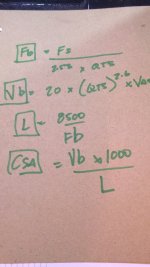
1. Start with the optimum size and length for the straight TL (let's call this Vb and Fb) using the equations I provided, then
2. Choose the usable bandwidth, BW of the TL (defined by ratio BW=Fh/(6*Fb where BW >=6*Fb) . In other words BW is always 1 or greater.
3. Calculate the required L of the TL from L=6*c*100/(4*BW*Fb)
4. Determine the starting CSA using S1=S2=S3=Vb/L
5. Now, setting S2 calculation to automatic, increase S1 and decrease S3 by the same amounts until the required Fb is achieved. This can be done by a goal-seek routine in Hornresp.
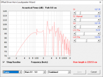
The end result should be a tapered TL with an Fb and low frequency cutoff very similar to a straight TL of the same volume. In fact, a quick Hornresp sim suggests that the response might actually improve (likely an end-correction issue - I really haven't looked into it.)
Here's an example - a Hornresp sim starting with a straight TL (grey response curve) and then adjusted like I outlined above (red response curve). The net volume, Vb, has not changed, but the passband response is improved with the use of a taper.

In other words, the design process could be like this (probably needs to be checked!):
1. Start with the optimum size and length for the straight TL (let's call this Vb and Fb) using the equations I provided, then
2. Choose the usable bandwidth, BW of the TL (defined by ratio BW=Fh/(6*Fb where BW >=6*Fb) . In other words BW is always 1 or greater.
3. Calculate the required L of the TL from L=6*c*100/(4*BW*Fb)
4. Determine the starting CSA using S1=S2=S3=Vb/L
5. Now, setting S2 calculation to automatic, increase S1 and decrease S3 by the same amounts until the required Fb is achieved. This can be done by a goal-seek routine in Hornresp.
The end result should be a tapered TL with an Fb and low frequency cutoff very similar to a straight TL of the same volume. In fact, a quick Hornresp sim suggests that the response might actually improve (likely an end-correction issue - I really haven't looked into it.)
Here's an example - a Hornresp sim starting with a straight TL (grey response curve) and then adjusted like I outlined above (red response curve). The net volume, Vb, has not changed, but the passband response is improved with the use of a taper.
On another note, I tried using my sample driver in a few of the suggested TL designs...
Here's the MK2006 result. At 230 litres, that box is way too big for this driver, and it shows in the response curve.

Here's the MK2021 result. Now the box is way too small...!

Here's the result using my method for a straight TL...

...and here's a tapered TL of the same volume Vb and resonant frequency, Fb, BW set to around 1.79

Here's the MK2006 result. At 230 litres, that box is way too big for this driver, and it shows in the response curve.
Here's the MK2021 result. Now the box is way too small...!
Here's the result using my method for a straight TL...
...and here's a tapered TL of the same volume Vb and resonant frequency, Fb, BW set to around 1.79
Attachments
Just to clarify - is the volume equation Vb = 20 * (Qts * 3.3) * Vas, or Vb = 20 * (Qts ^ 3.3) * Vas?given by equations that I provided earlier, e.g. Vb=20*Qts*3.3*Vas.
Would the inputs be Qts, Vas, Fs and Fh?In other words, the design process could be like this (probably needs to be checked!):
1. Start with the optimum size and length for the straight TL (let's call this Vb and Fb) using the equations I provided, then
2. Choose the usable bandwidth, BW of the TL (defined by ratio BW=Fh/(6*Fb where BW >=6*Fb) . In other words BW is always 1 or greater.
3. Calculate the required L of the TL from L=6*c*100/(4*BW*Fb)
4. Determine the starting CSA using S1=S2=S3=Vb/L
5. Now, setting S2 calculation to automatic, increase S1 and decrease S3 by the same amounts until the required Fb is achieved. This can be done by a goal-seek routine in Hornresp.
Rather than having Fh as an input could bandwidth in Hz (BWfreq) be used instead, with BW = (Fb + BWfreq) / (6 * Fb)?
Would the offset length L12 be determined using an offset ratio of 0.341 in all cases?
In step 5, would finding Vb rather than Fb give the same outcome?
Because a parabolic profile is assumed, Vb = 1 /2 * (S1 + S3) * L. Starting with S1 = S3 and then making S1new = S1old + Sdelta and S3new = S3old - Sdelta results in the volume remaining as Vb. Because the Vb condition is met for any value of Sdelta how would the optimum taper be determined?
Sigh, it's 20*(Qts^3.3)* Vas
At least, that's the curve-fit one for the optimum vented enclosure Vb for a particular driver (based on its t/s parameters).
I've also tried 20*(Qts^3)* Vas, which gives a larger box and lower tuning and seems to work for a number of drivers as well.
This weekend I'm going to have some free time on my hands, so I'll see if there's a way to come up with an equation to describe the relationship between BW and taper rate, so once one is provided, the other can be calculated.
Would the inputs be Qts, Vas, Fs and Fh?
Rather than having Fh as an input could bandwidth in Hz (BWfreq) be used instead, with BW = (Fb + BWfreq) / (6 * Fb)?
Would the offset length L12 be determined using an offset ratio of 0.341 in all cases?
In step 5, would finding Vb rather than Fb give the same outcome?
Because a parabolic profile is assumed, Vb = 1 /2 * (S1 + S3) * L. Starting with S1 = S3 and then making S1new = S1old + Sdelta and S3new = S3old - Sdelta results in the volume remaining as Vb. Because the Vb condition is met for any value of Sdelta how would the optimum taper be determined?
The inputs could be Qts, Vas, Fs and Fh. Or Qts, Vas, Fs and BW. Or Qts, Vas, Fs and taper rate (once I figure out how they're related, LOL).
Going with Qts, Vas, Fs and BW I think would be the best approach, and set BW to vary between values 1 and 2. Any higher than that and the mouth gets a bit too small (in my example, a BW of 1.79 ended up with the vent being 76 cm^2 (and a taper of 12.9:1), which is pretty small for a 12" subwoofer.
In step 5, the taper rate has to be adjusted to hit the target Fb, while keeping Vb constant. Once Fb is achieved, the optimum taper rate has been achieved. I don't know how to calculate the required taper rate of a TL to achieve a target Fb, so either a goal seek process or a curve fit will need to be used. I dunno, maybe Martin's tables could be used - I really haven't looked at them, and perhaps I should.
Oh, I forgot, that 0.341 is a bit of a ratch and only applies to straight TLs. It quickly reduces to 0.33 once the TL is tapered. I think it's another end-correction issue (the simple equations I provided ignore the impact of end corrections, as they're mainly for giving a good starting TL alignment, not the most optimized one ).
).or a volumetric pressure/velocity issue seen in air ejectors and sand blasters and things that create vacuum to change phase(ironically) in steam to condensate at the end of the turbine in a power plant(same issue) to send it back thru the steam generator (connection to the reactorplant coolant for example .Oh, I forgot, that 0.341 is a bit of a ratch and only applies to straight TLs. It quickly reduces to 0.33 once the TL is tapered. I think it's another end-correction issue (the simple equations I provided ignore the impact of end corrections, as they're mainly for giving a good starting TL alignment, not the most optimized one
physics if the ‘shape’ is not a taper’ in these cases either. you’re chasing a mathematical mistake or never looked at the right s
think to start ? and a shape that you can’t have
a differential pressure(fulcrum of this change) at the location of the driver is key to offset driver as well
look at two stroke exhausts ever ?
look at sine /cosine? suck and blow ? this is key to a ‘bellows’ too
convergent/divergent nozzle tap point
pi/9
Last edited:
This is consistent with Martin's comment: "The older alignment tables tended to produce a very large enclosure compared to a bass reflex design", and is the reason why he decided to change his method.Here's the MK2006 result. At 230 litres, that box is way too big for this driver, and it shows in the response curve.
I gathered from Martin's comment: "Also using the LDC BR alignment tables a lot more potential geometries are available that produce different enclosure volumes by accounting for different alignments (BB4, SC4, and QB3) as well as different amounts of box losses QL", that the user would need to select the most appropriate Vance Dickason table for a given design. In further email correspondence, Martin has clarified that for a transmission line system only the QL = 15 tables really need to be considered, so in the next update I will add the QL15/QB3/SQB3 (chart 2.6) and QL15/SC4/C4 (chart 2.9) alignments as options. The existing alignment in Method MK 2021 is QL15/SBB4/BB4 (chart 2.3).Here's the MK2021 result. Now the box is way too small...!
If your equation Fb = (Vas / Vb) ^ 0.31 * Fs applies, then for a given Vas and Fs, Fb won't change if Vb is kept constantIn step 5, the taper rate has to be adjusted to hit the target Fb, while keeping Vb constant.
.- Home
- Loudspeakers
- Subwoofers
- Hornresp