Hi Dan,
Why not just use the existing ABC option?
Kind regards,
David
Doh

Thanks, David
Kool. With proper tuning you can get greater gain out of a bandpass box than out of most "tapped" horn designs.
Tradeoff is the bandpass box is hard on drivers. People tend to turn them up loud and expect output beyond their designed for passband.
I stopped making them 25 years ago because of that reason.
Does a FLH = a positive flare port BP4?
How about a TH = a series tuned dual positive flare port BP6?
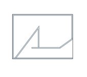
Hi David. I'm attempting to get the exported schematic of a rectangular three segment parabolic con horn into CAD but am struggling to understand how to define the perimeter of a dam (a six sided shape with two parallel sides and two tapered which is what I think each line defines) with the .txt.
For reference, here is the first three lines of my exported schematic:
Length (cm) Area (sq cm) Side Len (cm) Height/2 (cm) Top Len (cm) Width/2 (cm) Width Flare
0.000000 108.800000 0.000000 1.133333 0.000000 24.000000 Con
6.000000 138.605000 6.000000 1.443802 6.008027 24.000000 Con
12.000000 168.410000 12.000000 1.754271 12.016054 24.000000 Con
Last edited:
Hi David. I'm attempting to get the exported schematic of a rectangular three segment parabolic con horn into CAD but am struggling to understand how to define the perimeter of a dam (a six sided shape with two parallel sides and two tapered which is what I think each line defines) with the .txt.
For reference, here is the first three lines of my exported schematic:
Length (cm) Area (sq cm) Side Len (cm) Height/2 (cm) Top Len (cm) Width/2 (cm) Width Flare
0.000000 108.800000 0.000000 1.133333 0.000000 24.000000 Con
6.000000 138.605000 6.000000 1.443802 6.008027 24.000000 Con
12.000000 168.410000 12.000000 1.754271 12.016054 24.000000 Con
Hi Steve,
If the width is constant, use divide area by the width to determine height. What CAD package are you using?
Does a FLH = a positive flare port BP4?
How about a TH = a series tuned dual positive flare port BP6?
I tried until my head hertz. What are you talking about man!
FLH = Front Loaded Horn (I think)
TH = Tapped Horn
Are you suggesting some type of all in one enclosure?
Does a FLH = a positive flare port BP4?
Almost
.As far as Hornresp is concerned, the only difference is that the BP4 includes an end correction at the port inlet, whereas the FLH does not have end correction at the horn throat. This is why there will be a tuning difference in the results when comparing a BP4 against an equivalent FLH, as shown in the attachments.
Attachments
Hi David. I'm attempting to get the exported schematic of a rectangular three segment parabolic con horn into CAD but am struggling to understand how to define the perimeter of a dam (a six sided shape with two parallel sides and two tapered which is what I think each line defines) with the .txt
Hi StainlessSteve,
Just to clarify, is the problem not knowing what the Hornresp data represents, or is it not knowing how to load the data into CAD?
Kind regards,
David
I tried until my head hertz. What are you talking about man!
FLH = Front Loaded Horn (I think)
TH = Tapped Horn
Are you suggesting some type of all in one enclosure?
Correct.
No.
You stated "With proper tuning you can get greater gain out of a bandpass box than out of most "tapped" horn designs.
Tradeoff is the bandpass box is hard on drivers. People tend to turn them up loud and expect output beyond their designed for passband.
I stopped making them 25 years ago because of that reason."
My point is that FLH/TH and BP4/BP6 are similar enclosures so they should not have prevented you from building them in the past 25 years.
FLH/BP4 = sealed rear chamber/ported front chamber.
TH/BP6 = ported front & rear chambers.
The flare of the port signifies the enclosure type and alters the frequency response, group delay, phase response, etc.
Though, a straight flare tapped horn can also be modeled as an offset driver series tuned BP6.
Almost
As far as Hornresp is concerned, the only difference is that the BP4 includes an end correction at the port inlet, whereas the FLH does not have end correction at the horn throat. This is why there will be a tuning difference in the results when comparing a BP4 against an equivalent FLH, as shown in the attachments.
Less than 10% error in tuning frequency!
Actually, I thought you were going to compare a positive flare port FLH against a straight flare port BP4.
Actually, I thought you were going to compare a positive flare port FLH against a straight flare port BP4.
I felt that it was more important to highlight the difference between the simulation models - one includes an end correction (BP4), whereas the other does not (FLH). If the end correction is set to zero, the results become identical.
I leave it to you to compare a positive flare port FLH against a straight flare port BP4, if you feel that it would be a worthwhile exercise to undertake
.I felt that it was more important to highlight the difference between the simulation models - one includes an end correction (BP4), whereas the other does not (FLH). If the end correction is set to zero, the results become identical.
I leave it to you to compare a positive flare port FLH against a straight flare port BP4, if you feel that it would be a worthwhile exercise to undertake
With this comment, I'm beginning to understand that my concept of BP1Fanataic's post is probably incorrect. His references to the various horn types is as David has shown is pertaining to the configurations available in the new bandpass enclosure designs. And I have not looked at this myself either.
Ignorance can be a dangerous thing!
Regarding BP1fanatics question about why I stopped making bandpass enclosures.
I started out in this business like many here. I made enclosures and slapped in other peoples drivers into them. I made them for commercial reasons. And I found that people who wanted a bandpass enclosure were adept at killing their woofers. That was for a few reasons. The only design resources I had at the time (late 80's) was the AES paper that Earl Geddes and Mark Gander on the subject. I gathered enough information out of that paper to be able to calculate an optimal design configuration out of a given drivers specs. But I had no way to measure a driver parameters easily, and no way to do any simulations like we have today. Clients would destroy their woofers quite quickly and there was a return, and it was my fault of course! I mean I had my hand on the volume knob in their car each and every day after all. ( Right) So no more bandpass boxes for me. I simply couldn't afford the driver attrition rates.
Now in regards to Sound Quality.
In top place I place the various designs I have built in this order:
FRONT LOADED HORN (Has low distortion and awesome dynamics)
OPEN BAFFLE (With a large enough set of drivers it can have a low distortion sound if the driver is inherently low distortion. Not as great on the dynamics front compared to a FLH In a dula driver per side face to face configuration can have really useful room coupling pattern)
SEALED BOX ( Can be low distortion. Ultimately depends on driver design and linearity. Lacks the dynamics and impact capability of the FLH)
VENTED BOX (Can be very linear with a correctly sized port. Trade off is that the port is usually quite long when you do this and can increase your box size accordingly)
BANDPASS AND TAPPED HORN
(I lump these together for a few reasons. An extremely well designed tapped horn with have 7 to 8db of gain over the free air efficiency of a driver. So will an optimally designed bandpass enclosure. Both depend on the harmonics generated by the enclosure system to fill in the dip in the response if you want more than an octave of useful bandwidth out of the system. You cannot pick the harmonics you generate in a resonant system. And it those harmonics that extra additions to the input signal to the enclosure that I do not like to listen to. Some people in tests I have done with a few dozen listeners like that addition to the sound. When resonant low frequency systems are used to reproduce popular electronically amplified music they find the effect pleasing. The same people did not like the clarity of reproduction afforded by the front loaded horn in this test. A clean undistorted reproduction takes apart sloppy producing effects applied to recordings.)
My critique is long enough so I'll end it with this little paragraph.
I have played in and listed to live everything that you can hear in western music. I have played French Horn for 6 years in school, and played at the back of the orchestra right near the high impact drums and cymbals. The Brass section is not exactly quiet either. I've played at harpsichords, spinets, pipe organs and grand pianos in live acoustic spaces (played at means I'm not an accomplished keyboardist, I noodle around) I have a well trained set of ears. And to my ears king of low frequency reproduction is the Front Loaded Horn.
Sorry for the long post
Great post Mark!
So how come people don't treat BP4's like FLH? I see FLH designs where they require to use highpass filters, delay, power limiters, etc. I would think the design principles applied to a FLH can be used with a BP4.
Now that would make sense! Back when I was doing them there were no such animals available to us mere mortals. All that equipment existed in the pro-sound world, but not in the car audio market.
Things have advanced just a little bit I'd say. Not the least of them being able to accurately test the drivers and model the possible enclosures without making so much saw dust.
hi david i didnt find u very long time. hope u will fine. today i want to ask about something to u. can u make the option on hornresp ? now i think to design small flh which i want small sealed chamber. so i think if the hornresp has the Linkwitz Transform option. it will be good. if its possible u can put it likes winisd.
thank
thank
can u make the option on hornresp ? now i think to design small flh which i want small sealed chamber. so i think if the hornresp has the Linkwitz Transform option. it will be good. if its possible u can put it likes winisd.
Hi Thawach,
If I understand correctly, you would like to be able to simulate the effect of using a Linkwitz Transform type equaliser circuit to improve the low-frequency performance of a small front-loaded horn that is in effect acting as a bass-reflex loudspeaker.
There are no plans to include such a feature in Hornresp.
Kind regards,
David
Doh
Thanks, David
Hi Dan,
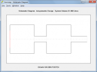
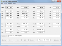
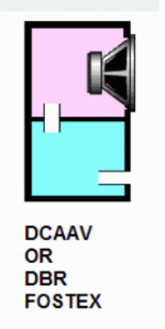
Just to complete the picture, the "DCAAV OR DBR FOSTEX" system shown in Attachment 1 could be simulated without end corrections, as shown in Attachments 2 and 3.
Kind regards,
David
Attachments
Hornresp Update 4800-180829
Hi Everyone,
CHANGE
An explanatory note has been added to the Filter Wizard section of the Help file to indicate that in some parametric equaliser software packages, the shelving filter 'Q Factor' is actually S, a "shelf slope" parameter. The relationship between Q and S is given by the expression:
S = 1 / (((1 / Q) ^ 2 - 2) / (10 ^ (G / 40) + 1 / (10 ^ (G / 40))) + 1)
Where:
S = shelf slope parameter
Q = Q factor
G = gain
The post linked below, and subsequent posts in the same thread, refer:
http://www.diyaudio.com/forums/software-tools/326106-hornresp-vs-sigma-studio.html#post5515421
BUG FIX
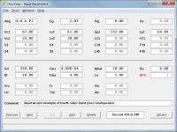
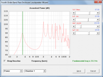
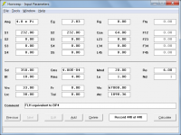
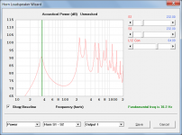
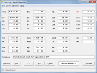
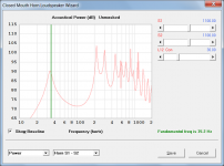
The internal end correction value for the port tube in a BP4 system was not being calculated correctly. This has now been fixed, and as a consequence the fundamental tuning frequency of the BP4 test example given in Post #8567 increases from 33.2 Hz to 35.2 Hz (see Attachment 1), which is closer to the fundamental frequency of 36.2 Hz previously calculated for the equivalent FLH system used in the comparison.
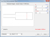
As a further sanity check, the above BP4 test example has now been compared against an equivalent closed-mouth FLH having a vented rear chamber (the port tube specified using Ap and Lpt has an internal end correction applied automatically). As should be the case, the results for the two systems are identical - see Attachments 1 to 4.
Kind regards,
David
Hi Everyone,
CHANGE
An explanatory note has been added to the Filter Wizard section of the Help file to indicate that in some parametric equaliser software packages, the shelving filter 'Q Factor' is actually S, a "shelf slope" parameter. The relationship between Q and S is given by the expression:
S = 1 / (((1 / Q) ^ 2 - 2) / (10 ^ (G / 40) + 1 / (10 ^ (G / 40))) + 1)
Where:
S = shelf slope parameter
Q = Q factor
G = gain
The post linked below, and subsequent posts in the same thread, refer:
http://www.diyaudio.com/forums/software-tools/326106-hornresp-vs-sigma-studio.html#post5515421
BUG FIX
The internal end correction value for the port tube in a BP4 system was not being calculated correctly. This has now been fixed, and as a consequence the fundamental tuning frequency of the BP4 test example given in Post #8567 increases from 33.2 Hz to 35.2 Hz (see Attachment 1), which is closer to the fundamental frequency of 36.2 Hz previously calculated for the equivalent FLH system used in the comparison.
As a further sanity check, the above BP4 test example has now been compared against an equivalent closed-mouth FLH having a vented rear chamber (the port tube specified using Ap and Lpt has an internal end correction applied automatically). As should be the case, the results for the two systems are identical - see Attachments 1 to 4.
Kind regards,
David
Attachments

Last edited:
- Home
- Loudspeakers
- Subwoofers
- Hornresp