Dear Brian,
Thanks for the info. I was running through the Input wizard using offset . There are certain parameters I am not clear of. I wonder what should I put in for these questions that popped up.
Rear chamber?
Should it be "no rear Chamber"?
Throat Chamber?
Should it be "no throat Chamber"
I also seem to be able to do it from
Direct radiator -> transmission line-> mass loaded.
Unlike the example given, this one has the speaker driver somewhere in the middle and I could adjust segment 1.
Any thoughts on this?
Thanks.
Oon
Dear Brian,
Thanks for the info. I was running through the Input wizard using offset . There are certain parameters I am not clear of. I wonder what should I put in for these questions that popped up.
Rear chamber?
Should it be "no rear Chamber"?
Throat Chamber?
Should it be "no throat Chamber"
I also seem to be able to do it from
Direct radiator -> transmission line-> mass loaded.
Unlike the example given, this one has the speaker driver somewhere in the middle and I could adjust segment 1.
Any thoughts on this?
Thanks.
Oon
"No rear chamber" and "no front chamber" are correct for a simple mass-loaded transmission line sim in Hornresp. Once the schematic illustration in Hornresp matches the topology of what you intend to build, you're on the right track.
Hornresp Update 4250-180222
Hi Everyone,
CHANGE 1
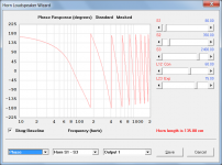
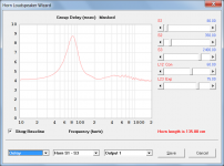
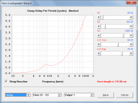
Phase Response, Group Delay and Group Delay Per Period charts have been added to the Loudspeaker Wizard, and to the Filter Wizard when selected from the Loudspeaker Wizard. Attachments 1 to 3 refer.
CHANGE 2
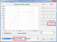
1. With the Loudspeaker Wizard Power output option selected, SPL magnitude and phase values can be exported to a .txt or .frd file by either clicking the Export Data button in the Memory & Width window or by pressing the F9 function key.
2. With the Loudspeaker Wizard Impedance output option selected, electrical impedance magnitude and phase values can be exported to a .txt or .zma file by either clicking the Export Data button in the Memory & Width window or by pressing the F9 function key.
3. With the Loudspeaker Wizard Displacement output option selected, diaphragm displacement values can be exported to a .txt or .csv file by either clicking the Export Data button in the Memory & Width window or by pressing the F9 function key.
Attachment 4 refers.
CHANGE 3
The Help file Efficiency description now makes it clear that the power conversion efficiency value does not include the effect of filters. Post #8047 refers.
BUG FIX
The Group Delay Per Period chart in the Filter Wizard was not taking into account the delay due to the filter. Changing the filter settings made no difference to the results. This has now been fixed.
Kind regards,
David
Hi Everyone,
CHANGE 1
Phase Response, Group Delay and Group Delay Per Period charts have been added to the Loudspeaker Wizard, and to the Filter Wizard when selected from the Loudspeaker Wizard. Attachments 1 to 3 refer.
CHANGE 2
1. With the Loudspeaker Wizard Power output option selected, SPL magnitude and phase values can be exported to a .txt or .frd file by either clicking the Export Data button in the Memory & Width window or by pressing the F9 function key.
2. With the Loudspeaker Wizard Impedance output option selected, electrical impedance magnitude and phase values can be exported to a .txt or .zma file by either clicking the Export Data button in the Memory & Width window or by pressing the F9 function key.
3. With the Loudspeaker Wizard Displacement output option selected, diaphragm displacement values can be exported to a .txt or .csv file by either clicking the Export Data button in the Memory & Width window or by pressing the F9 function key.
Attachment 4 refers.
CHANGE 3
The Help file Efficiency description now makes it clear that the power conversion efficiency value does not include the effect of filters. Post #8047 refers.
BUG FIX
The Group Delay Per Period chart in the Filter Wizard was not taking into account the delay due to the filter. Changing the filter settings made no difference to the results. This has now been fixed.
Kind regards,
David
Attachments
...long time Hornresp user here. Thanks again for the program!
I have a question that I've been researching with no luck.
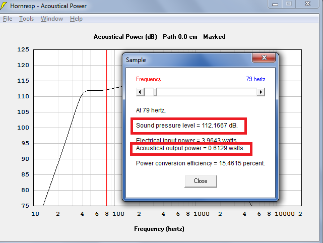
In efficiency, the acoustic power used to be 112.17db = 1 acoustic watt (for 2 pi space).
Now it is showing 0.61 acoustic watts at 112.17db. This obviously gives very different efficiency results.
Could someone explain this or point me to where this was changed and the rationale?
Thanks in advance!
I have a question that I've been researching with no luck.
In efficiency, the acoustic power used to be 112.17db = 1 acoustic watt (for 2 pi space).
Now it is showing 0.61 acoustic watts at 112.17db. This obviously gives very different efficiency results.
Could someone explain this or point me to where this was changed and the rationale?
Thanks in advance!
Attachments

Could someone explain this or point me to where this was changed and the rationale?
Hi publius,
It was a bug, reported by Sabbelbacke in Post #4179, and subsequently fixed. It applied to combined responses only.
http://www.diyaudio.com/forums/subwoofers/119854-hornresp-418.html#post3810728
Kind regards,
David
With the Loudspeaker Wizard Power output option selected, SPL magnitude and phase values can be exported to a .txt or .frd file by either clicking the Export Data button in the Memory & Width window or by pressing the F9 function key.
Thanks for this David. I'm now able to compare the measured response of my stuffed POC6 with the corresponding Hornresp sim. Considering the limitations of the measurement (transfer-function approach that introduced a bit too much noise above 150 Hz and below 35 Hz), the result is almost identical for the passband I was aiming for.
Note that I did line up the curves SPL wise, so there is the possibility that the POC's actual response is a dB or so what Hornresp predicts, but even then, the correlation is so close that I'm going to try to repeat the measurement again this weekend just to confirm it LOL.
Thanks!
Attachments
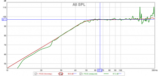
Thanks for this David. I'm now able to compare the measured response of my stuffed POC6 with the corresponding Hornresp sim. Considering the limitations of the measurement (transfer-function approach that introduced a bit too much noise above 150 Hz and below 35 Hz), the result is almost identical for the passband I was aiming for.
Note that I did line up the curves SPL wise, so there is the possibility that the POC's actual response is a dB or so what Hornresp predicts, but even then, the correlation is so close that I'm going to try to repeat the measurement again this weekend just to confirm it LOL.
Thanks!
Awesome!
Nice to see a measurement line up with a simulation Brian.
Thanks for this David. I'm now able to compare the measured response of my stuffed POC6 with the corresponding Hornresp sim. Considering the limitations of the measurement (transfer-function approach that introduced a bit too much noise above 150 Hz and below 35 Hz), the result is almost identical for the passband I was aiming for.
Note that I did line up the curves SPL wise, so there is the possibility that the POC's actual response is a dB or so what Hornresp predicts, but even then, the correlation is so close that I'm going to try to repeat the measurement again this weekend just to confirm it LOL.
Thanks!
Hi Brian,
Thanks for the feedback.
The comparison looks almost too good to be true - it would certainly be worthwhile checking that the result is indeed repeatable
") .
.Kind regards,
David
Hi publius,
It was a bug, reported by Sabbelbacke in Post #4179, and subsequently fixed. It applied to combined responses only.
http://www.diyaudio.com/forums/subwoofers/119854-hornresp-418.html#post3810728
Kind regards,
David
Just to clarify - system efficiency was changed from 'total acoustical output power' / 'total electrical input power' to 'net acoustical output power' / 'total electrical input power' with the release of Product Number 3300-131130. The error reported by Sabbelbacke was inadvertently introduced at that time. The change from total to net acoustical power is the reason why the old value of 1 acoustic watt is reduced to 0.61 acoustic watts in the example provided by 'publius'. The power difference seen is not caused by the bug, which was quickly fixed.
Hello David & fellow members,
Do you know how should I best simulate an down-firing front loaded horn, as TuneAudio Anima?
I wonder about Solid Radiation Angle, and maybe if there is a way to 'include' the floor gain in the simulation.
TUNE AUDIO ANIMA | TuneAudio
Thank you!
Do you know how should I best simulate an down-firing front loaded horn, as TuneAudio Anima?
I wonder about Solid Radiation Angle, and maybe if there is a way to 'include' the floor gain in the simulation.
TUNE AUDIO ANIMA | TuneAudio
Thank you!
Hello David & fellow members,
Do you know how should I best simulate an down-firing front loaded horn, as TuneAudio Anima?
I wonder about Solid Radiation Angle, and maybe if there is a way to 'include' the floor gain in the simulation.
TUNE AUDIO ANIMA | TuneAudio
Thank you!
You simulate it into 1 Pi space.
But keep in mind a few provisos. This simulation will only reflect a measurement if you place this loudspeaker in a basement where the floor and walls are truly reflective across the audio spectrum. On a conventional wood floor it is actually acoustically transparent in the lower bass frequencies and you will not measure exactly what you simulated.
Hi M1 Audio,
After having another look at the loudspeaker systems shown in your Post #7936, if I am interpreting the designs correctly, it appears that it may be possible to simulate all four in Hornresp as different variants of tapped horns.
SYSTEM 1 - Simulate as shown in Attachment 1.
(Values for Ap1 and Lp can also be specified, if so desired).
SYSTEM 2 - Simulate as shown in Attachment 2 or in Attachment 3.
If simulated as shown in Attachment 3 (Model 2 considers half the total system and one driver) use the Multiple Speakers tool to specify the complete system as 2 speakers in parallel.
SYSTEM 3 - Simulate one of the 3 horn cabinets as shown in Attachment 4 or in Attachment 5.
Use the Multiple Speakers tool to specify the 3 cabinets making up the complete system.
SYSTEM 4 - Simulate as shown in Attachment 6 or in Attachment 1.
If simulated as shown in Attachment 1 use the Multiple Speakers tool to specify the complete system as 2 speakers in series together with 2 speakers in parallel.
Kind regards,
David
Then David ...
It took me a while to respond, due to some unforeseen
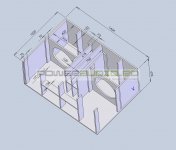
But anyway, maybe I was not so clear in my doubt. With respect to Annexes 1 and 4, yes, they fit as Tapped Horn's. As for annexes 2 and 3, they are horns with ducts in series, where:
Annex 1 is a version of Planar Horn, modified by a designer here in Brazil.
Annex 2, is a medium horn with duct at the mouth of the throat.
I would like to know how to configure Hornresp for the soft stuffing of this duct in series on these horns. Here are some new photos attached to these same models.
Attachments
Then David ...
It took me a while to respond, due to some unforeseen
But anyway, maybe I was not so clear in my doubt. With respect to Annexes 1 and 4, yes, they fit as Tapped Horn's. As for annexes 2 and 3, they are horns with ducts in series, where:
Annex 1 is a version of Planar Horn, modified by a designer here in Brazil.
Annex 2, is a medium horn with duct at the mouth of the throat.
I would like to know how to configure Hornresp for the soft stuffing of this duct in series on these horns. Here are some new photos attached to these same models.
Hi M1 Audio,
Sorry, but I am not sure how to interpret the information contained in your post
.As far as adding filling material is concerned, it can be specified using the Loudspeaker Wizard tool.
With regard to the design configuration shown in your Attachment 1, it would probably need to be simulated using AkAbak. There are limits on what Hornresp can do.
(If anyone else can help out with answers for M1 Audio, then please do not hesitate to do so).
Kind regards,
David
Then David ...
It took me a while to respond, due to some unforeseen
But anyway, maybe I was not so clear in my doubt. With respect to Annexes 1 and 4, yes, they fit as Tapped Horn's. As for annexes 2 and 3, they are horns with ducts in series, where:
Annex 1 is a version of Planar Horn, modified by a designer here in Brazil.
Annex 2, is a medium horn with duct at the mouth of the throat.
I would like to know how to configure Hornresp for the soft stuffing of this duct in series on these horns. Here are some new photos attached to these same models.
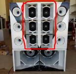
Based on the area circled in red you could conceivably model this in hornresp.
The drivers are close enough to each other that they will essentially behave as a composite driver until the reproduced wavelength is shorter than that of the cone area. You can model one half as a driver horn combination by modeling one driver and the corresponding mouth area occupied by one of the drivers in the stack. In other words divide the driver mouth area into three and model a driver into that amount of horn area. Then you could use the multiple driver tool to model them as a composite set of drivers. It would get you in the ballpark of what the true output could be.
Hornresp will be next asked to model the sound of a butterfly flapping with only one wing
Hi David,
A member at the diyma forum gave me an idea of how you could make some money off of hornresp*. (If you're interested.)
Here's the idea:
Parts Express has been fairly active in developing loudspeaker software. For instance, forum member Bill Waslo has contributed to their loudspeaker measurement software. What if you added a method of retrieving driver parameters from Parts Express?
Basically the way this would work is that Hornresp would be able to pull driver parameters from PE. But there would also be a button where the Hornresp user can purchase the driver. Basically click the button and hornresp directs them to the Parts Express page. And then get PE to give you a cut of each sale.
This is fairly similar to how podcasters make their money; they have a link on their app, and it takes you to Amazon. The podcasters get a cut of the sale on Amazon.
Of course, all of this would require two things from Parts Express:
1) They'd need to expose an API on their website that provides T/S parameters. This is pretty easy to do, I've written things like this in four hours or so.
2) The trickier parts is that they'd have to agree to a sponsorship program! Basically a program to give you a cut of the sales that originate from Hornresp.
Maybe this is a far out idea, but it might work...
(original thread his here: Somebody smart needs to script up a way - Car Audio | DiyMobileAudio.com | Car Stereo Forum)
Hi David,
A member at the diyma forum gave me an idea of how you could make some money off of hornresp*. (If you're interested.)
Here's the idea:
Parts Express has been fairly active in developing loudspeaker software. For instance, forum member Bill Waslo has contributed to their loudspeaker measurement software. What if you added a method of retrieving driver parameters from Parts Express?
Basically the way this would work is that Hornresp would be able to pull driver parameters from PE. But there would also be a button where the Hornresp user can purchase the driver. Basically click the button and hornresp directs them to the Parts Express page. And then get PE to give you a cut of each sale.
This is fairly similar to how podcasters make their money; they have a link on their app, and it takes you to Amazon. The podcasters get a cut of the sale on Amazon.
Of course, all of this would require two things from Parts Express:
1) They'd need to expose an API on their website that provides T/S parameters. This is pretty easy to do, I've written things like this in four hours or so.
2) The trickier parts is that they'd have to agree to a sponsorship program! Basically a program to give you a cut of the sales that originate from Hornresp.
Maybe this is a far out idea, but it might work...
(original thread his here: Somebody smart needs to script up a way - Car Audio | DiyMobileAudio.com | Car Stereo Forum)
Hi PB,
Many thanks for the suggestion, but I can see how such a move would have the potential to complicate my life in all sorts of ways, and I prefer to keep things as simple as possible
.When it comes to Hornresp, money has never been a motivating factor - I like developing and supporting the program just for the fun of it, and for the "brain exercise" it provides. Very early users such as Bill Geiger (whgeiger) may recall that I originally intended charging $10 for the software, but ended up giving it away free - even to those who were prepared to pay for it
.Kind regards,
David
Based on the area circled in red you could conceivably model this in hornresp.
The drivers are close enough to each other that they will essentially behave as a composite driver until the reproduced wavelength is shorter than that of the cone area. You can model one half as a driver horn combination by modeling one driver and the corresponding mouth area occupied by one of the drivers in the stack. In other words divide the driver mouth area into three and model a driver into that amount of horn area. Then you could use the multiple driver tool to model them as a composite set of drivers. It would get you in the ballpark of what the true output could be.
Thanks Mark.
Hornresp will be next asked to model the sound of a butterfly flapping with only one wing
Before starting on the coding, just to clarify - would the said insect be located in 2Pi or 4Pi space?
.They must be inside by 7pm
My my, must be genuine juvenile butterflies

Just to clarify - system efficiency was changed from 'total acoustical output power' / 'total electrical input power' to 'net acoustical output power' / 'total electrical input power' with the release of Product Number 3300-131130. The error reported by Sabbelbacke was inadvertently introduced at that time. The change from total to net acoustical power is the reason why the old value of 1 acoustic watt is reduced to 0.61 acoustic watts in the example provided by 'publius'. The power difference seen is not caused by the bug, which was quickly fixed.
Thank you.
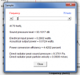
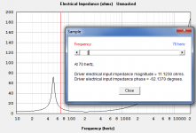
Now, I am stumped on the input side, electrical input power. I thought Real AC power was defined:
P = e^2 / Z * cos(theta); where cos(theta) = Re/Z
which reduces to e^2 / Z^2 * Re
but that gives significantly different results than what is shown in Hornresp, so I must have the wrong equation.
Putting some numbers to it:
e = 1.84
Re = 3.4
Z at 70Hz = 11.123
plugging into the above equation gives P = 0.0930 watts
Hornresp indicates 0.2802 watts electrical input power at 70Hz.
Where have I gone wrong?
Attachments
- Home
- Loudspeakers
- Subwoofers
- Hornresp