Hi Everyone,
CHANGE 1
...
CHANGE 2
...
CHANGE 3
...
BUG FIX
...
Kind regards,
David
Absolutely incredible. Didn't take you long either.
Maybe it's time to focus your wizardry on adding more segments. (LOL just joking. Seriously though, apart from more segments and being able to analyze at any node in the enclosure, Hornresp is almost as fully functional as Akabak now. And as we know, Hornresp has a bunch of stuff Akabak doesn't - stuff I couldn't live without anymore now that you've spoiled us so.)
Having said that - is it possible to analyze at any node? I realize it's super selfish to ask for more right after such a huge update, but I'm just wondering. If we could analyze at any node we could do stuff like check velocity inside a flared port, not just at the ends.
Aside from more segments (which I know isn't going to happen) I don't think I would ever need to use Akabak for anything else other than analyzing at nodes inside the enclosure.
Fantastic work and I can't wait to try the new features. I don't have time today but I'm really excited about this update. Thanks so much.
Hi just a guy,
Unfortunately no - it falls into the same category as 'more segments'") .
.
Hornresp does not use a generalised nodal network analysis model. A complete re-write would be required, which is not going to happen .
If you are interested in checking the maximum particle velocity, then for a flared port this will normally be at the end having the smaller cross-sectional area.
You're most welcome - thanks for the thanks. Your request prompted me to re-visit all aspects of the filter functionality (something I would not have done otherwise) resulting in hopefully a better product.
Kind regards,
David
is it possible to analyze at any node?
Unfortunately no - it falls into the same category as 'more segments'
.Hornresp does not use a generalised nodal network analysis model. A complete re-write would be required, which is not going to happen
.If we could analyze at any node we could do stuff like check velocity inside a flared port, not just at the ends.
If you are interested in checking the maximum particle velocity, then for a flared port this will normally be at the end having the smaller cross-sectional area.
Thanks so much.
You're most welcome - thanks for the thanks. Your request prompted me to re-visit all aspects of the filter functionality (something I would not have done otherwise) resulting in hopefully a better product.
Kind regards,
David
A user has reported via email that "Version 41.00 crashes immediately with a message 'Error 13' mismatch".
I have now managed to generate the error myself, simply by removing the existing data file.
I will try to fix the problem as soon as possible.
Hello David,
Would it be possible to incorporate a voltage limit into the "Max SPL" graph?
We would then have diaphragm excursion / amplifier power / voltage as limiting conditions. Actually I'd like to see current as well but between limiting power and voltage both, that is taken care of. I understand that technically the max voltage is already specified in the input values. I would find this very useful as part of the max SPL graph though. It needs to be looked at in context with the driver excursion and current, or amplifier power. The amplifier to speaker interaction is complex and the system limitations vary between excursion, amplifier voltage limits and amplifier current limitations depending on the impedance and frequency. The current way of specifying power and excursion often results in unrealistic voltages unavailable for the amplifier.
Perhaps it would be possible to even add a check box next to each limiting parameter so that one , two or all could be looked at individually or all together?
Thanks,
I lika the idea!
I have to say that I run into similar application examples. Pushing drivers to their limits is part of good engineering. Keeping with in their safe operating area is better engineering.
I try to do the latter. It is possible to go back and forth from the input screen and Power screen as I am doing now. And pull out the calculator and extract the amperes into the load. But having that available will be very useful.
Hello David,
Would it be possible to incorporate a voltage limit into the "Max SPL" graph?
We would then have diaphragm excursion / amplifier power / voltage as limiting conditions. Actually I'd like to see current as well but between limiting power and voltage both, that is taken care of. I understand that technically the max voltage is already specified in the input values. I would find this very useful as part of the max SPL graph though. It needs to be looked at in context with the driver excursion and current, or amplifier power. The amplifier to speaker interaction is complex and the system limitations vary between excursion, amplifier voltage limits and amplifier current limitations depending on the impedance and frequency. The current way of specifying power and excursion often results in unrealistic voltages unavailable for the amplifier.
Perhaps it would be possible to even add a check box next to each limiting parameter so that one , two or all could be looked at individually or all together?
Thanks,
I have to say that I run into similar application examples. Pushing drivers to their limits is part of good engineering. Keeping with in their safe operating area is better engineering.
I try to do the latter. It is possible to go back and forth from the input screen and Power screen as I am doing now. And pull out the calculator and extract the amperes into the load. But having that available will be very useful.
Hi David:
Thanks for the filter wizard changes.
I like the way that its one set of filters whether you activate from the input screen or the power/tools menu. Initially one creates the filters in the power/tools/filterwizard path and then can save them, and then go back and turn them on in input/tools and then look at things like driver power after equalization.
I did this, closed HR, did some other stuff, re-opened HR and found my fliter settings had all gone away (all bands off). I went through that loop a second time and the same thing happened. The problem was repeatable, at least for those two trials.
Is anybody else seeing equalizer filter parameters not saved after an F9 in the filter wizard then close both the filter wizard and HR and then re-open HR?
Jack
Hi just a guy,
Unfortunately no - it falls into the same category as 'more segments'
Hornresp does not use a generalised nodal network analysis model. A complete re-write would be required, which is not going to happen
If you are interested in checking the maximum particle velocity, then for a flared port this will normally be at the end having the smaller cross-sectional area.
Kind regards,
David
Oh well, you can't have everything. I think I just thought of a way to do the flared port analysis anyway. It's the part in the middle that I need to check, not at either of the ends, but I think I know how to do that now without resorting to drastic measures like Akabak. I guess I could just leave one of the flared ends off, check velocity, make sure it doesn't exceed port core limits, then add the flare. Seems kind of obvious now that I think about it.
Thanks anyway, it's all appreciated.
Hi David.
Could you consider adding the ability to save previous curves on the graph? I'd like to be able to see the 'before and after' curves for any small change I make to the design.
Ideally, we should be able to step certain variables through a number of values by specifying the range and step size. The graph would then show curves for each combination.
I want to design a horn with an (truncated) oblate spheroid section followed by a conical section. Any suggestions?
Is anybody else seeing equalizer filter parameters not saved after an F9 in the filter wizard then close both the filter wizard and HR and then re-open HR?
Hi Jack,
Just a thought - when you re-open Hornresp, are you looking at the same record that you saved the filter settings to? The saved filter settings only apply to the record in use at the time of saving. Different records can have different filter settings. There is not just one set of common settings applying to all records.
(Everything seems to be working fine at my end).
Kind regards,
David
Hi just a guy,
I would like to better understand your requirements. Would it be possible to post the schematic diagram for a typical example design, or ideally for multiple different example designs, showing the point or points at which you would like to check the particle velocity? Also, would you want to know the pressure at those points, or is just particle velocity sufficient?
I am not sure that will give you the answer you are looking for, unfortunately.
Kind regards,
David
It's the part in the middle that I need to check, not at either of the ends,
I would like to better understand your requirements. Would it be possible to post the schematic diagram for a typical example design, or ideally for multiple different example designs, showing the point or points at which you would like to check the particle velocity? Also, would you want to know the pressure at those points, or is just particle velocity sufficient?
I guess I could just leave one of the flared ends off, check velocity, make sure it doesn't exceed port core limits, then add the flare.
I am not sure that will give you the answer you are looking for, unfortunately
.Kind regards,
David
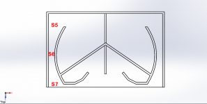
Sure, here's two examples of flared ports, the first is just traditional flares at the ends, the second is the entire port being flared as popularized by Danley recently (his only ported box offering uses this style).

I'd like to check velocity at any point between the flares in the first example (doesn't matter where) and at the pinch point in the second example.
I can't think of any reason to check pressure but it would be nice to know velocity. Flare It gives acceptable limits for chuffing and for core velocity in the port itself (regardless of whether there's a flare or not). It's the velocity at the narrowest point in the port that I would like to see, this is the core velocity. I can easily design for 10 m/s or less at the port ends using Hornresp's current functionality (with or without flares) but as it stands you can only check the core velocity if there's no flare (you can't check in the middle of the port).
Last edited:
Hi SamAnytime,
The existing Compare tool is as far as I am prepared to go with regard to showing 'before and after' results.
Compare Tool:
Displays the current and previous or captured acoustical impedance, acoustical power, acoustical pressure, electrical impedance, diaphragm displacement, phase response, group delay or beam width results on the same chart.
Previous results are used in comparisons by default. Press Ctrl+C to capture the current results or Ctrl+R to release captured results. Results can also be captured or released by right-clicking on any chart.
Press F4 to show or hide the previous or captured results.
It's not going to happen.
For multiple segment horns, the Loudspeaker Wizard shows in real time the effect of changing parameter values, and has the ability to temporarily store and recall up to four different sets of values. A baseline can be set for comparison purposes.
It cannot be done using Hornresp.
After the initial throat section, the profile of an oblate spheroidal waveguide is very close to a conical flare anyway, so why go to the trouble of truncating the OSW and adding a separate conical segment? Changing to a different flare rate from that generated by simply extending the OSW would compromise the overall design concept.
Kind regards,
David
Could you consider adding the ability to save previous curves on the graph?
The existing Compare tool is as far as I am prepared to go with regard to showing 'before and after' results
.Compare Tool:
Displays the current and previous or captured acoustical impedance, acoustical power, acoustical pressure, electrical impedance, diaphragm displacement, phase response, group delay or beam width results on the same chart.
Previous results are used in comparisons by default. Press Ctrl+C to capture the current results or Ctrl+R to release captured results. Results can also be captured or released by right-clicking on any chart.
Press F4 to show or hide the previous or captured results.
Ideally, we should be able to step certain variables through a number of values by specifying the range and step size. The graph would then show curves for each combination.
It's not going to happen
.For multiple segment horns, the Loudspeaker Wizard shows in real time the effect of changing parameter values, and has the ability to temporarily store and recall up to four different sets of values. A baseline can be set for comparison purposes.
I want to design a horn with an (truncated) oblate spheroid section followed by a conical section. Any suggestions?
It cannot be done using Hornresp.
After the initial throat section, the profile of an oblate spheroidal waveguide is very close to a conical flare anyway, so why go to the trouble of truncating the OSW and adding a separate conical segment? Changing to a different flare rate from that generated by simply extending the OSW would compromise the overall design concept.
Kind regards,
David
I'd like to check velocity at any point between the flares in the first example (doesn't matter where) and at the pinch point in the second example.
I can't think of any reason to check pressure but it would be nice to know velocity.
Hi just a guy,
Thanks for the prompt response. I was hoping that you would post something like the designs you show
.Just to confirm that I understand correctly, in effect what you are asking for is the ability to check the particle velocity at the interface points between the segments in a multiple segment horn. In the worst case (a port tube assembly specified using a throat adaptor and four segments) this would be at the following points:
S0 (Throat adaptor entry)
S1
S2
S3
S4
S5 (Port Outlet)
Is this correct?
Kind regards,
David
Would it be possible to incorporate a voltage limit into the "Max SPL" graph?
Hi Josh,
I will have to think about that one for a while
.I can already foresee a few problems, and no doubt other issues will pop up as I look into things further.
You will have to leave it with me for a time, to 'cogitate' over
.Kind regards,
David
- Home
- Loudspeakers
- Subwoofers
- Hornresp