Just wondering - will we be able to see the new value of Bl?
Hi just a guy,
I hadn't intended displaying the adjusted Bl value, but it could certainly be made available if required. The value is currently not shown in the Loudspeaker Wizard because I couldn't see the need, and thought it could be confusing.
Kind regards,
David
I am trying to find a way of implementing the feature you requested without having to make wholesale changes to Hornresp. I am not sure if it is possible or not, but I will keep you posted on any progress.
I have to concede defeat
") .
.The request falls into the same category as the provision of more segments - it is just too difficult to implement - it's not going to happen.
Out of interest I did however hack directly into the Hornesp code, bypassing the user interface, and by working with two "jury-rigged" records in tandem, was able to see the effect on throat acoustical impedance of having a Le Cléac'h flare at the mouth of an axisymmetric OS waveguide. As expected, the magnitudes of the ripples in the impedance are reduced somewhat, meaning that the power response will be marginally smoother, but the overall effect is not great, and certainly not enough to warrant rewriting large parts of the program to accommodate the feature
.Thanks ...
for tying. I want to explore the domain of mouth curvature vs coverage angle to determine where the 'sweet spot' territory is. Keels's treatment of horn mouth dimensions (circa 1973) needs an upgrade. If you consider how the brass instruments work, their relatively large, curved mouth lips encourage reflectance rather than mitigate it. So there is a lot more to this than just throwing a arbitrarily curved flare onto an equally arbitrarily determined horn bell.
Regards,
Bill
I have to concede defeat
The request falls into the same category as the provision of more segments - it is just too difficult to implement - it's not going to happen.
Out of interest I did however hack directly into the Hornesp code, bypassing the user interface, and by working with two "jury-rigged" records in tandem, was able to see the effect on throat acoustical impedance of having a Le Cléac'h flare at the mouth of an axisymmetric OS waveguide. As expected, the magnitudes of the ripples in the impedance are reduced somewhat, meaning that the power response will be marginally smoother, but the overall effect is not great, and certainly not enough to warrant rewriting large parts of the program to accommodate the feature
for tying. I want to explore the domain of mouth curvature vs coverage angle to determine where the 'sweet spot' territory is. Keels's treatment of horn mouth dimensions (circa 1973) needs an upgrade. If you consider how the brass instruments work, their relatively large, curved mouth lips encourage reflectance rather than mitigate it. So there is a lot more to this than just throwing a arbitrarily curved flare onto an equally arbitrarily determined horn bell.
Regards,
Bill
Last edited:
Hi just a guy,
I hadn't intended displaying the adjusted Bl value, but it could certainly be made available if required. The value is currently not shown in the Loudspeaker Wizard because I couldn't see the need, and thought it could be confusing.
Kind regards,
David
I think it would be quite useful in certain cases, I would personally like to see the new value for Bl even if it's hidden somewhere.
I want to explore the domain of mouth curvature vs coverage angle to determine where the 'sweet spot' territory is.
Hi Bill,
In that case I don't feel so bad
.Even if it had been possible to implement the Obl + Lec option in Hornresp, the system would have been analysed as a two-segment horn, and the Directivity tools would not have been available for use anyway. I assume that you would need them to determine the 'sweet spot' territory?
Kind regards,
David
I think it would be quite useful in certain cases, I would personally like to see the new value for Bl even if it's hidden somewhere.
Hi just a guy,
Just confirming that the adjusted Bl value will be provided, and that it won't be too difficult to find
.Kind regards,
David
I just started playing around with Hornresp after using other solutions and always feeling like I needed something more - first, I wanted to say thank you and that I appreciate your contributions and time developing such a comprehensive software for free. It seems like it is very robust and a powerful tool once I get the hang of it. I will run a sim on a previous design that I know performs and functions a certain way to make sure I am populating the fields correctly because it looks like I am missing a few things - the response isn't simulating how I feel it should for the parameters so I imagine there is user/human error involved.
I am just playing with sealed direct radiators for now to get the hang of it. First for EG the plots are totally different if I set it to 0 vs the max voltage I will hit it with. The response looks like it is more accurate to how the driver should perform with a value of 0 vs the max voltage. I am modeling a 10in driver and the F3 is way too high when I add the voltage where the data cant be accurate but when left at 0 it seems like it is simulating pretty close to how it should perform. Is 0 or 1 a better value to keep this set at for direct radiators?
FR values - airflow resistivity of enclosures acoustical lining. How do I get this value or what should the default value be? When you are asking for acoustical lining, I assume you are referring to the material that I actually line the enclosure with? I normally use a foam that looks similar to the Auralex stuff and I spray with hardeners to get it to the desired results. I have used other materials like the 3m matting that's typically used under hardwood flooring and plan to use experiment with other materials in the near future as well. What should I use as a value for FR since I have no idea what the materials resistance is and even if I can find out I typically modify it as well which would change the airflow resistance.
TAL - Acoustical lining thickness - I guess this ties into FR and is easy enough to measure however I do not know the FR.
In some designs I use poly batting or insulation as a filler - Where would FR1 and TAL1 be input because I do not see it on the input screen - Also how do I get the value for the fill materials or is there a general default that I should use? I am going to continue to experiment, read and watch tutorials but if you can please assist me with some of the questions asked above, I would greatly appreciate it.
Thanks
Jared
Yes
Hi David,
You are absolutely correct.
Design in this domain has entirely different priorities.
Regards,
Bill
Hi Bill,
In that case I don't feel so bad
Even if it had been possible to implement the Obl + Lec option in Hornresp, the system would have been analysed as a two-segment horn, and the Directivity tools would not have been available for use anyway. I assume that you would need them to determine the 'sweet spot' territory?
Kind regards,
David
Hi David,
You are absolutely correct.
Design in this domain has entirely different priorities.
Regards,
Bill
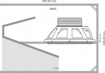
I have designed one compound horn box.
Need guidance about input in Hornresp.
Atc & Vtc still confuse me.
Hi jayam000,
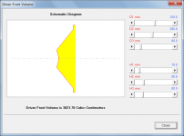
For your design set Atc = Sd and Vtc = the air volume in front of the driver cone.
The required Vtc value can be found using the Driver Front Volume tool.
Kind regards,
David
Attachments
Hi Jared,
Suggest you leave Eg at the default value of 2.83 volts, which is equivalent to 1 watt into a nominal 8 ohm resistive load.
(Setting Eg = 0 gives the driver diaphragm a constant rms velocity of 10 cm/sec).
If you don't have a specific Fr value, use the default value of 40000 mks rayls/m or simply select the "Resonances Masked' option, to suppress enclosure resonances.
Fr1 and Tal1 are only available in the Loudspeaker Wizard - but not for a sealed direct radiator system. To fill a sealed direct radiator system, increase the value of Tal while looking at the Loudspeaker Wizard schematic diagram, until the enclosure is completely filled.
If you don't know the fill material value, use the Fr default of 40000 mks rayls/m, or alternatively, select the 'Resonances Masked' option.
Kind regards,
David
I am modeling a 10in driver and the F3 is way too high when I add the voltage where the data cant be accurate but when left at 0 it seems like it is simulating pretty close to how it should perform. Is 0 or 1 a better value to keep this set at for direct radiators?
Suggest you leave Eg at the default value of 2.83 volts, which is equivalent to 1 watt into a nominal 8 ohm resistive load.
(Setting Eg = 0 gives the driver diaphragm a constant rms velocity of 10 cm/sec).
What should I use as a value for FR since I have no idea what the materials resistance is and even if I can find out I typically modify it as well which would change the airflow resistance.
If you don't have a specific Fr value, use the default value of 40000 mks rayls/m or simply select the "Resonances Masked' option, to suppress enclosure resonances.
In some designs I use poly batting or insulation as a filler - Where would FR1 and TAL1 be input because I do not see it on the input screen - Also how do I get the value for the fill materials or is there a general default that I should use?
Fr1 and Tal1 are only available in the Loudspeaker Wizard - but not for a sealed direct radiator system. To fill a sealed direct radiator system, increase the value of Tal while looking at the Loudspeaker Wizard schematic diagram, until the enclosure is completely filled.
Also how do I get the value for the fill materials or is there a general default that I should use?
If you don't know the fill material value, use the Fr default of 40000 mks rayls/m, or alternatively, select the 'Resonances Masked' option.
Kind regards,
David
for tying. I want to explore the domain of mouth curvature vs coverage angle to determine where the 'sweet spot' territory is. Keels's treatment of horn mouth dimensions (circa 1973) needs an upgrade. If you consider how the brass instruments work, their relatively large, curved mouth lips encourage reflectance rather than mitigate it. So there is a lot more to this than just throwing a arbitrarily curved flare onto an equally arbitrarily determined horn bell.
Regards,
Bill
Hi Bill,
If you want to do directivity simulations, you may want to take a look at the Mode Matching Method I have been working on for some years. It takes into account higher order modes in the horn, and compares well with BEM. MPM Toolbox
-Bjørn
Dr Kolbrek,
looks like you have not updated your Profile.
looks like you have not updated your Profile.
PhD Candidate
Hello I've recently re-downloaded hornresp due to my computer deciding to commit cybercide and have think i've found a bug with the new version. Adjusting Vrc in the loudspeaker wizard and also on the main screen don't affect the graph. I've tried changing type of enclosure and other things but it doesn't do anything. Can post pics if needs be but just wanted to ask if anyone else has had the a similar problem. Regards
Absolutely
Hi Bjørn,
First, thank you very much for sharing your work with me.
Hopefully in the near future, I will have the opportunity to reciprocate.
I have downloaded the MPM Toolbox files referenced in you private message.
I am about to purchase and download a current "personal" version of MatLab.
What customization options do I need to include? Those mandatory? And those nice to have?
As an aside, I just bought a HP Z2 Mini Workstation [1] & [2] for my wife. It is configured with a Xeon 4-Core Processor, Invidia Graphics Card, ECN Memory and a Tetra-byte Hard drive. HP's design is impressive. I call it a "cool operator" and it runs stealthy silent as well. Anyone in the market for a new workstation may want to consider one of these. (BTW I am not an HP employee nor do I own stock in the company)
Regards,
Bill
[1] Z2 Internals Animation
HP Z2 Mini Workstation | HP® Official Store
[2] Z2 Configuration Page
Configure
Hi Bill,
If you want to do directivity simulations, you may want to take a look at the Mode Matching Method I have been working on for some years. It takes into account higher order modes in the horn, and compares well with BEM. MPM Toolbox
-Bjørn
Hi Bjørn,
First, thank you very much for sharing your work with me.
Hopefully in the near future, I will have the opportunity to reciprocate.
I have downloaded the MPM Toolbox files referenced in you private message.
I am about to purchase and download a current "personal" version of MatLab.
What customization options do I need to include? Those mandatory? And those nice to have?
As an aside, I just bought a HP Z2 Mini Workstation [1] & [2] for my wife. It is configured with a Xeon 4-Core Processor, Invidia Graphics Card, ECN Memory and a Tetra-byte Hard drive. HP's design is impressive. I call it a "cool operator" and it runs stealthy silent as well. Anyone in the market for a new workstation may want to consider one of these. (BTW I am not an HP employee nor do I own stock in the company)
Regards,
Bill
[1] Z2 Internals Animation
HP Z2 Mini Workstation | HP® Official Store
[2] Z2 Configuration Page
Configure
Last edited:
Adjusting Vrc in the loudspeaker wizard and also on the main screen don't affect the graph.
Nope, got the current 170420 and both work fine.
GM
Leach Effect Perhaps? WHG
Couple of problems with this name (although I do kinda like it).
1. The lossy inductance issue isn't that well known, as I've found out by hanging out at avs forum. Even the people that are well aware of the issue are not using the feature. (Most by far are using WinISD and ignoring my data). As far as I know, only a very few people have used this feature so far. So most people wouldn't intuitively understand "Leach Effect" any better than "Lossy Le". It's a topic that isn't discussed much at all, and before about 20 years ago there wasn't really any reason to consider it because there were no grossly offending drivers wrt to lossy inductance.
2. Leach wasn't the only one to quantify complex inductance, come up with complex inductance t/s parameters and write a paper on the issue. I'm not sure he was even the first to do this.
Even the Leach paper you linked to has Inductance Losses in the title, which is exactly what Ricci and I have proposed - Lossy Le. That's the issue at hand and no other name seems to fit as well.
EDIT - if there's room for "Inductance Losses" on the Hornresp GUI that would be the best name. It's self explanatory and technically the same thing as "Lossy Le".
Last edited:
Hi Bjørn,
First, thank you very much for sharing your work with me.
Hopefully in the near future, I will have the opportunity to reciprocate.
I have downloaded the MPM Toolbox files referenced in you private message.
I am about to purchase and download a current "personal" version of MatLab.
What customization options do I need to include? Those mandatory? And those nice to have?
Hi Bill,
You're welcome.
I've mainly been using the Academic version of Matlab, which has most of the toolboxes included, so I'm not sure which ones you need. I think my code should run on a bare-bones Matlab installation. Apart from the sinc function which is needed for rectangular horns, and which is part of the signal processing toolbox, but you can easily code that function yourself.
Bjørn
HiNope, got the current 170420 and both work fine.
GM
Ive now managed to fix it by deleting the whole driver file and created a new one (not a problem since ivw got no real data on there), seems to work fine now. Just a bit strange it just seemed to stop working whilst fiddling about with porting an offset driver sim..?
- Home
- Loudspeakers
- Subwoofers
- Hornresp