I managed to locate what i think is similar to the post i mentioned.
Thanks Zero D.
Hornresp Update 4020-161125
Hi Everyone,
CHANGE 1
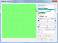
Wavefront Simulator custom designs can now be permanently saved by selecting the 'Save Current Design' option. Saved designs can subsequently be retrieved by selecting the 'Open Saved Design' option. Saved design files are stored in the 'Waves' sub-folder, automatically created the first time that the latest release is run. See Attachment 1.
The specification of Wavefront Simulator source delays has been simplified, and source delay values expressed in degrees now remain as specified when the frequency setting is changed.
CHANGE 2
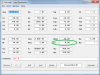
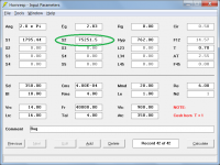
The value of driver voice coil inductance Le can now be set to zero. This change was requested by a user investigating the performance of high frequency acoustical waveguides and their associated drive units. See Attachment 2.
BUG FIX
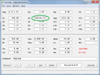
Under certain conditions it was possible to enter an area value containing nine characters (format nnnnnn.nn) into the S2 input box for a hyperbolic-exponential horn. This has now been fixed so that the maximum number of characters is eight, with the S2 area format being automatically set to either nnnnn.nn or nnnnnn.n depending upon the horn mouth size. See Attachment 3.
NOTE
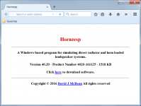
The Hornresp download site page has been simplified to show only essential information, and now also makes reference to direct radiator loudspeaker systems. See Attachment 4.
Kind regards,
David
Hi Everyone,
CHANGE 1
Wavefront Simulator custom designs can now be permanently saved by selecting the 'Save Current Design' option. Saved designs can subsequently be retrieved by selecting the 'Open Saved Design' option. Saved design files are stored in the 'Waves' sub-folder, automatically created the first time that the latest release is run. See Attachment 1.
The specification of Wavefront Simulator source delays has been simplified, and source delay values expressed in degrees now remain as specified when the frequency setting is changed.
CHANGE 2
The value of driver voice coil inductance Le can now be set to zero. This change was requested by a user investigating the performance of high frequency acoustical waveguides and their associated drive units. See Attachment 2.
BUG FIX
Under certain conditions it was possible to enter an area value containing nine characters (format nnnnnn.nn) into the S2 input box for a hyperbolic-exponential horn. This has now been fixed so that the maximum number of characters is eight, with the S2 area format being automatically set to either nnnnn.nn or nnnnnn.n depending upon the horn mouth size. See Attachment 3.
NOTE
The Hornresp download site page has been simplified to show only essential information, and now also makes reference to direct radiator loudspeaker systems. See Attachment 4.
Kind regards,
David
Attachments
Hi David can I throw some 'beer money' your way as appreciation of your work?
Hi USRFobiwan,
Many thanks for your kind offer, but just knowing that Hornresp is appreciated and being put to good use, is more than enough
") .
.Kind regards,
David
Hornresp Update 4020-161126
Hi Everyone,
BUG FIX
In some cases the S2 input box for a hyperbolic-exponential horn was still not showing the correct format.
Values with seven characters rather than eight were being displayed - see attachment.
Hopefully this problem has now been fixed - finally.
Kind regards,
David
Hi Everyone,
BUG FIX
In some cases the S2 input box for a hyperbolic-exponential horn was still not showing the correct format.
Values with seven characters rather than eight were being displayed - see attachment.
Hopefully this problem has now been fixed - finally.
Kind regards,
David
Attachments
Hornresp Update 4020-161201
Hi Everyone,
CHANGE
The Wavefront Simulator source time delay upper limit has been increased from 5 milliseconds to 10 milliseconds (equivalent to a one wavelength delay at 100Hz).
BUG FIX 1
In some cases the Input Wizard would generate an invalid system specification when the 'Multiple entry' option was initially selected and a change then made to a different option. The following sequence of events, for example, would generate an incorrect result.
Free space
Next > Horn loaded
Next > Multiple entry
Next > 2 segments
Back > Multiple entry
Back > Direct radiator
Next > Sixth order band pass
Next > …
BUG FIX 2
Source delays for systems saved in the Wavefront Simulator were not being retrieved when the saved system was subsequently re-opened.
The above two bugs have now been fixed.
Kind regards,
David
Nice.
This is getting more and more useful.
Can a horn simulation be configured as a dual entry on the throat yet with a compression chamber?
I have a high SPL planar horn to design and I'm grappling with how to work that one out.
Two planars in a sandwich and a common horn throat.
Trouble is that it would not be on a conical horn. To many sources of distortion on a conic for this application.
Can a horn simulation be configured as a dual entry on the throat yet with a compression chamber?
Hi Mark,
Not sure that I understand
.Why can't it simply be simulated as a system with two drivers sharing a common compression chamber?
(I suspect I must be missing something here).
Kind regards,
David
Hi GM,
Not sure
.It's unclear to me how Mark's references to "two planars in a sandwich" and "compression chamber" should be interpreted.
Kind regards,
David
It's Mark with low blood sugar. Hypoglycemia is almost the same as being drunk. And I make for lot's of laughs when I cannot finish simple sentences.
The question is in a nutshell can a multiple driver horn be something other than a conic?
I have a R&D idea where I can use two planars in very close proximity. Basically face to face. With the appropriate throat adapter and a phase plug.
As far as I have seen to now the multiple entry horn simulations are only done with conics.
How about a LeCleach?
They are turning out to be my favorite mid to high frequency horns?
Would this appropriately be called a tinny sounding horn?
Hi GM,
Not sure
It's unclear to me how Mark's references to "two planars in a sandwich" and "compression chamber" should be interpreted.
Kind regards,
David
Hopefully there is a bit of a clarification. I'll see if I can put up a napkin sketch.
Would this appropriately be called a tinny sounding horn?
Actually, they don't.
Regardless, do you mean a Unity/Synergy concept or simply two horns with a flat side 'pancaked' together with a common throat?
Either way, it seems like doubling horns, then it's just a matter of how you 'slice n' dice it' makes it a dual horn on a common dual driver throat......or maybe it's just my morning hypoglycemia/caffeine withdrawal making all things possible.
GM
It's Mark with low blood sugar. Hypoglycemia is almost the same as being drunk. And I make for lot's of laughs when I cannot finish simple sentences.
The question is in a nutshell can a multiple driver horn be something other than a conic?
I have a R&D idea where I can use two planars in very close proximity. Basically face to face. With the appropriate throat adapter and a phase plug.
As far as I have seen to now the multiple entry horn simulations are only done with conics.
How about a LeCleach?
They are turning out to be my favorite mid to high frequency horns?
There have been some Synergies built on Tractrix flares. (See thread below which isn't about the flare but some exemplars where tractrix. I think there was a "Trynergy" thread by XRK971 where the goal was to Synergy on a tractrix but I couldn't find it.)
http://www.diyaudio.com/forums/multi-way/285030-bookshelf-multi-way-point-source-horn.html
I would have had trouble seeing how you would sandwich two planar drivers without a killing reflection null showing up, except for the photo GM showed, which come to think of it doesn't lead to a sandwich. You might be better off with two panels side by side in a single throat/chamber.
Or add a third driver on the back wall of the chamber, then low pass the sidewall drivers below the point of the reflection null.
Last edited:
I would have had trouble seeing how you would sandwich two planar drivers without a killing reflection null showing up, except for the photo GM showed, which come to think of it doesn't lead to a sandwich. You might be better off with two panels side by side in a single throat/chamber.
Or add a third driver on the back wall of the chamber, then low pass the sidewall drivers below the point of the reflection null.
Not that hard. The trick is in doing it properly.
The simulation is a dry run before I take it to the real world.
The two driver competing with each other and potentially cancelling out each other is not something that is new to engineer around. It is pretty much how compression drivers designed. Without a phase cancellation compensation plug they do not work very well either.
A little out of the box thinking for a very hi end very high efficiency horn system.
I can go the good old empirical route of cut and try. But doing a simulation first is most practical in the long run. A proper simulation makes most of the dry run of a what see what happens all done in the confines of an easy to change computer simulation. That is my preferred route. Sim first and build second.
you are preaching to the choir re' simulation.Not that hard. The trick is in doing it properly.
The simulation is a dry run before I take it to the real world.
The two driver competing with each other and potentially cancelling out each other is not something that is new to engineer around. It is pretty much how compression drivers designed. Without a phase cancellation compensation plug they do not work very well either.
A little out of the box thinking for a very hi end very high efficiency horn system.
I can go the good old empirical route of cut and try. But doing a simulation first is most practical in the long run. A proper simulation makes most of the dry run of a what see what happens all done in the confines of an easy to change computer simulation. That is my preferred route. Sim first and build second.
Now perhaps I can see it. Does your phase plug separate the chamber in half so each driver sees only the exit and not the other driver?
Measure Twice, Cut Once ...
is the gist of it.
In GM's photo, at the point of convergence, there will be some reflectance taking place that returns acoustic energy to the diaphragm. It will be frequency dependent and occur for small wave lengths that are comparable to the converging apertures.
Two plainer surfaces vibrating in opposition will have issues when their dimensions are comparable to wavelength. Boundary conditions, including the compliance barrier (front to back isolation), internal panel acoustics, and enclosure limits are all at issue in ways similar to those of a conventional CD. The assumed large surface areas will require a phasing plug for the very same reasons as well. Current CD implementations use opposing ring diaphragms to facilitate the necessary geometry. e.g.: JBL D2, BMS 4599ND, or the BMS 4508ND [1]?. WHG
[1] Overview
Not that hard. The trick is in doing it properly.
The simulation is a dry run before I take it to the real world.
The two driver competing with each other and potentially cancelling out each other is not something that is new to engineer around. It is pretty much how compression drivers designed. Without a phase cancellation compensation plug they do not work very well either.
A little out of the box thinking for a very hi end very high efficiency horn system.
I can go the good old empirical route of cut and try. But doing a simulation first is most practical in the long run. A proper simulation makes most of the dry run of a what see what happens all done in the confines of an easy to change computer simulation. That is my preferred route. Sim first and build second.
is the gist of it.
In GM's photo, at the point of convergence, there will be some reflectance taking place that returns acoustic energy to the diaphragm. It will be frequency dependent and occur for small wave lengths that are comparable to the converging apertures.
Two plainer surfaces vibrating in opposition will have issues when their dimensions are comparable to wavelength. Boundary conditions, including the compliance barrier (front to back isolation), internal panel acoustics, and enclosure limits are all at issue in ways similar to those of a conventional CD. The assumed large surface areas will require a phasing plug for the very same reasons as well. Current CD implementations use opposing ring diaphragms to facilitate the necessary geometry. e.g.: JBL D2, BMS 4599ND, or the BMS 4508ND [1]?. WHG
[1] Overview
Last edited:
- Home
- Loudspeakers
- Subwoofers
- Hornresp