Post #6817: "... the schematic diagram can be instantly checked from any other window by pressing and holding down the S key. Releasing the S key instantly reverts back..."
Hi Oliver,
You left out the important bit at the beginning:
"I assume that you may be using the Loudspeaker Wizard. If so, remember that …"
The S key feature only works with the Loudspeaker Wizard
") .
.If people think it might be useful though, I could look at extending the functionality to the main result windows as well.
Kind regards,
David
Last edited:
If people think it might be useful though, I could look at extending the functionality to the main result windows as well.
In the absence of any feedback - either for or against the idea - I have decided to proceed anyway
.The 'S key' instant schematic functionality will be extended to the main result windows in the next release.
Surprised you didn't hear it
Hi Mark,
Unfortunately my hearing is not as good as it once was - you will just have to think louder
.Kind regards,
David
Hornresp Update 4000-161108
Hi Everyone,
CHANGE 1
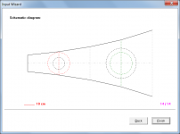
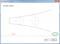
The last page of the Input Wizard tool now shows a schematic diagram of the specified loudspeaker system - see Attachment 1. Also, the red progress line has been removed and the percentage completed indicator has been replaced by an indicator showing the number of pages completed out of the total number of applicable pages - see Attachment 2. Pressing the Home key returns to the first page of the Input Wizard.
CHANGE 2
Pressing and holding down the S key while viewing the main form now instantly displays the schematic diagram. Releasing the S key immediately returns to the previously displayed chart or input parameters window.
Kind regards,
David
Hi Everyone,
CHANGE 1
The last page of the Input Wizard tool now shows a schematic diagram of the specified loudspeaker system - see Attachment 1. Also, the red progress line has been removed and the percentage completed indicator has been replaced by an indicator showing the number of pages completed out of the total number of applicable pages - see Attachment 2. Pressing the Home key returns to the first page of the Input Wizard.
CHANGE 2
Pressing and holding down the S key while viewing the main form now instantly displays the schematic diagram. Releasing the S key immediately returns to the previously displayed chart or input parameters window.
Kind regards,
David
Attachments
Forum for OD horns, "Synergy" style
Hello David
I realize this excellent forum is for Tapped horns only.
Do you have plans for opening a forum for OD horns like Tom Danley invented ?
Yes, I know, there are other fora for OD horns out there. Bill Waslo's for instance, making a valiant effort to simplify things.
Trouble is: I dont get it
I mean (to mention a few):
1.) He (and the followers) universally use S1 as 2,53 cm2.
But the horn surfaces all "aim-in" to a 0,7" square throat, being 3,2 cm2.
Then they drill a circular throat at 1" dia., being 5,6 cm2, twice the simulation !
To me, they simulate one horn, then build another.
2.) Where is the "tap" point ? I've got Ap1, yes, but at which distance from the throat ?
3). The distance inside the compression driver (about 4 acoustic cm) ? I have not seen anybody actually adressing, and simulating this conical horn section. Will Hornresp simulate "as if" the horn is closed at S1, ignoring the compression driver ?
A bit of guidance could be of interest to others than me, I think.
Hi David,
Is it possible to share deeper information about the driver diaphragm displacement ? How it's calculated? What is the best way to interpret the graphic taking into account any sound track?
Maybe it's oblivious for the majority but I'm still learning. This attribute have been a big constrain for my current TH design due to low Xmax drivers available at my country.
Thanks in advanced.
A bit of guidance could be of interest to others than me, I think.
Hi Barniboy,
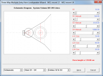
A Synergy type system (including the compression driver at S1 and the acoustic path length inside the driver) can be simulated using the Multiple Entry Horn Wizard. See the 'Multiple Entry Horn Wizard' description in the Tools Menu section and the 'Two-Way or Three-Way Multiple Entry Horn' description in the Loudspeaker Models section of the Hornresp Help file for details.
Kind regards,
David
Attachments
Hi Marcelo,
Hornresp determines the driver diaphragm velocity from an analysis of the complete electro-mechano-acoustical loudspeaker equivalent circuit and then calculates the driver diaphragm displacement as diaphragm velocity / (2 * Pi * frequency). Dr Bjørn Kolbrek has carried out tests showing the Hornresp diaphragm displacement predictions to be accurate when the loudspeaker is operated in the linear range (i.e. no power compression). There appears to a general misconception that the Hornresp diaphragm displacement predictions are too high, but Bjørn has showed that when measured using sophisticated test equipment, the predictions can be very accurate indeed.
http://www.diyaudio.com/forums/subwoofers/119854-hornresp-15.html#post1591527
The driver diaphragm is modelled as a rigid plane circular piston, driven by a sinusoidal signal. How to interpret results obtained under different conditions to these, I leave to you.
Kind regards,
David
Is it possible to share deeper information about the driver diaphragm displacement ? How it's calculated?
Hornresp determines the driver diaphragm velocity from an analysis of the complete electro-mechano-acoustical loudspeaker equivalent circuit and then calculates the driver diaphragm displacement as diaphragm velocity / (2 * Pi * frequency). Dr Bjørn Kolbrek has carried out tests showing the Hornresp diaphragm displacement predictions to be accurate when the loudspeaker is operated in the linear range (i.e. no power compression). There appears to a general misconception that the Hornresp diaphragm displacement predictions are too high, but Bjørn has showed that when measured using sophisticated test equipment, the predictions can be very accurate indeed.
http://www.diyaudio.com/forums/subwoofers/119854-hornresp-15.html#post1591527
What is the best way to interpret the graphic taking into account any sound track?
The driver diaphragm is modelled as a rigid plane circular piston, driven by a sinusoidal signal. How to interpret results obtained under different conditions to these, I leave to you
.Kind regards,
David
Hi David,
Post #6822: "In the absence of any feedback..."
So sorry I didn't keep up w/ this, but, you found the best possible solution.
Thank you!
Regards,
Hi Oliver,
Not a problem - I made an "executive decision" to proceed as I couldn't see any downside to including the feature, and it was relatively easy to implement anyway
.Kind regards,
David
8 driver t-line ugh
Hello all, I'm a newbie so please be kind. I have read every single page on this tl section and find each message more informing and more confusing. I want to build a t-line 1/4 wave for 8 4" Aura NS4-255-8D's. Main reason being they are so rare and robust. This is not a please tell me what box to build as I would really like to understand it all myself, but unfortunately Hornresp is out of my league when it comes to my learning curve. Any ideas or suggestions that anyone has would be greatly appreciated. I'm just trying to build a multi fold t-line with the lowest possible -3db I can accomplish with these little buggers, and I really want to use all 8. I'm even open to isobaric loading them. Thanks for reading this and for your time. I'll add some theil smalls ......
NS4-255-8D
4 inch Woofer
l High Excursion
l Very Low Distortion
l No Stray Magnetic Fields
l Wide Bandwidth
Nominal Diameter . . . . . . . . . . . . . .4 inches (105 mm)
Nominal Impedance (Z) . . . . . . . . . . 8 ohms
Sensitivity, 1W/1m (E) . . . . . . . . . . . 84 dB @ 1 kHz
Power Capacity, RMS (Pe) . . . . . . . . 20 W
Power Capacity, Peak . . . . . . . . . . . 40 W
Frequency Range (-10dB) . . . . . . . . 60 Hz - 6 kHz
Minimum Impedance . . . . . . . . . . . . 4 ohms
Voice Coil Diameter . . . . . . . . . . . . .25.5 mm
Voice Coil Winding Length (h) . . . . . 5.8 mm
Voice Coil Number of Layers . . . . 4
Voice Coil Former Material . . . . . . . .Kapton
Voice Coil Wire Composition . . . . . . Copper
Magnetic Material . . . . . . . . . . . . . . Neodymium radial
Stray Flux Shielding . . . . . . . . . . . . . Inherent
Magnetic Gap Depth (He) . . . . . . . . 16.7 mm
Cone Material . . . . . . . . . . . . . . . . . Anodized Aluminum
Surround Material . . . . . . . . . . . . . . Foamed Rubber
Polarity, Outward Motion . . . . . . . . . Positive voltage on (+) terminal
Net Weight . . . . . . . . . . . . . . . . . . . . 0.384 kg
Thiele / Small Parameters
Resonant Frequency (Fo) - Fs . . . . . 62 Hz
Voice Coil DC Resistance - Re . . . . . 6.17 ohms
Total Q - Qts . . . . . . . . . . . . . . . . . . 0.44
Mechanical Q - Qms . . . . . . . . . . . . 7.79
Electrical Q - Qes . . . . . . . . . . . . . . 0.47
Equivalent Volume of Air - Vas . . . . . 3.18 L
Radiating Piston Area - Sd . . . . . . . . 50.27 cm2
Electrical / Mechanical Parameters
Flux Density x Length - BL . . . . . . . . 6.12 Tesla-meters
Compliance - Cms . . . . . . . . . . . . . . 893 mm/N
Total Mass - Mms . . . . . . . . . . . . . .7.29 grams
Hello all, I'm a newbie so please be kind. I have read every single page on this tl section and find each message more informing and more confusing. I want to build a t-line 1/4 wave for 8 4" Aura NS4-255-8D's. Main reason being they are so rare and robust. This is not a please tell me what box to build as I would really like to understand it all myself, but unfortunately Hornresp is out of my league when it comes to my learning curve. Any ideas or suggestions that anyone has would be greatly appreciated. I'm just trying to build a multi fold t-line with the lowest possible -3db I can accomplish with these little buggers, and I really want to use all 8. I'm even open to isobaric loading them. Thanks for reading this and for your time. I'll add some theil smalls ......
NS4-255-8D
4 inch Woofer
l High Excursion
l Very Low Distortion
l No Stray Magnetic Fields
l Wide Bandwidth
Nominal Diameter . . . . . . . . . . . . . .4 inches (105 mm)
Nominal Impedance (Z) . . . . . . . . . . 8 ohms
Sensitivity, 1W/1m (E) . . . . . . . . . . . 84 dB @ 1 kHz
Power Capacity, RMS (Pe) . . . . . . . . 20 W
Power Capacity, Peak . . . . . . . . . . . 40 W
Frequency Range (-10dB) . . . . . . . . 60 Hz - 6 kHz
Minimum Impedance . . . . . . . . . . . . 4 ohms
Voice Coil Diameter . . . . . . . . . . . . .25.5 mm
Voice Coil Winding Length (h) . . . . . 5.8 mm
Voice Coil Number of Layers
. . . . 4Voice Coil Former Material . . . . . . . .Kapton
Voice Coil Wire Composition . . . . . . Copper
Magnetic Material . . . . . . . . . . . . . . Neodymium radial
Stray Flux Shielding . . . . . . . . . . . . . Inherent
Magnetic Gap Depth (He) . . . . . . . . 16.7 mm
Cone Material . . . . . . . . . . . . . . . . . Anodized Aluminum
Surround Material . . . . . . . . . . . . . . Foamed Rubber
Polarity, Outward Motion . . . . . . . . . Positive voltage on (+) terminal
Net Weight . . . . . . . . . . . . . . . . . . . . 0.384 kg
Thiele / Small Parameters
Resonant Frequency (Fo) - Fs . . . . . 62 Hz
Voice Coil DC Resistance - Re . . . . . 6.17 ohms
Total Q - Qts . . . . . . . . . . . . . . . . . . 0.44
Mechanical Q - Qms . . . . . . . . . . . . 7.79
Electrical Q - Qes . . . . . . . . . . . . . . 0.47
Equivalent Volume of Air - Vas . . . . . 3.18 L
Radiating Piston Area - Sd . . . . . . . . 50.27 cm2
Electrical / Mechanical Parameters
Flux Density x Length - BL . . . . . . . . 6.12 Tesla-meters
Compliance - Cms . . . . . . . . . . . . . . 893 mm/N
Total Mass - Mms . . . . . . . . . . . . . .7.29 grams
I was recently involved in a tl design thread. The post that shows how to design transmission lines in Hornresp is here - Enclosure design programs - Page 6 - AVS Forum | Home Theater Discussions And Reviews
For an 8 driver line you need to set the number of drivers to 8 (any series/parallel combination that equals 8 drivers and results in an impedance your amp will be happy with) and set S2 (actually L12) so S2 is at the midpoint of the 8 drivers since Hornresp can only simulate a single composite driver based on the t/s of the 8 drivers.
If you read that thread from the beginning we talk about the many various types of transmission lines and go over most of the Hornresp input boxes and what boxes to fill in for certain types of alignment. There's also a few hints and tips littered throughout the thread, like hover your mouse over an input box and look at the bottom of the Hornresp window to see what that box is for and what to input. And double clicking on most boxes in the input window will bring up a wizard to help you to input what is required for that box. This is especially helpful for the t/s parameters, but for most of the input boxes a double click will bring up a very useful wizard.
Also a fantastic primer paper on tl design is MJK's Alignment Tables article. This paper helps you design a tl and shows you what tl shape and length do to response, what effect t/s parameters have and what stuffing does. There's also a spreadsheet you can download from the same place that automates the design process for you so you don't have to do any math. This paper and spreadsheet are available at quarter-wave.com.
The drivers you have chosen are very small and very low sensitivity so the lowest possible f3 might not be a good choice. You could tune the box to 10 hz if you wanted to but that severely restricts your max spl. Once you start playing in Hornresp you will see that you can trade extension for spl.
Last edited:
Hornresp Update 4000-161110
Hi Everyone,
BUG FIX
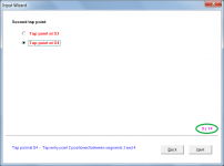
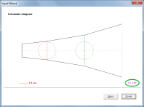
The Input Wizard page counter was not showing the correct total number of pages for a three segment tapped horn - see Attachment 1. This has now been fixed - see Attachment 2.
Kind regards,
David
Hi Everyone,
BUG FIX
The Input Wizard page counter was not showing the correct total number of pages for a three segment tapped horn - see Attachment 1. This has now been fixed - see Attachment 2.
Kind regards,
David
Attachments
Compression
Seems odd asking this on a subwoofer forum, but has anyone got any sort of rough idea of how to model a WE555 compression driver on Hornresp ?
I'm just doing a model of the WE13a horn to get a rough idea how the phase & group delay look over eg. 80Hz to 2000Hz. I wouldn't expect any params to be spot-on, or accurate at higher frequencies, but could do with a starting point.
has anyone got any sort of rough idea of how to model a WE555 compression driver on Hornresp ?
Hi IslandPink,
Set Eg = 0.
Kind regards,
David
- Home
- Loudspeakers
- Subwoofers
- Hornresp