Hi David
This new version of Hornresp with phase unwrapping is great, it offers a lot of functionality, but I still miss the ability to make it unwrap the phase with a delay value chosen by the user rather than the value that the program choses, which I often dislike Substracting the value entered from the group delay plot would be quite useful too.
Updating phase and group delay plots when the directivity option is used would be quite useful too, as I stated previously.
BTW: We love you anyway
This new version of Hornresp with phase unwrapping is great, it offers a lot of functionality, but I still miss the ability to make it unwrap the phase with a delay value chosen by the user rather than the value that the program choses, which I often dislike
Substracting the value entered from the group delay plot would be quite useful too.Updating phase and group delay plots when the directivity option is used would be quite useful too, as I stated previously.
BTW: We love you anyway
Hello,
I have try to simulate a standing wave in a tube (that's why I sent an e-mail to know the celerity of sound), but it's difficult to tune perfectly.
Anyway, it's almost possible: I have a quasi standing wave.
So, if i see a standing wave, i do not see the wave front, then it's not a wave front simulator but an acoustic amplitude simulator which does not the difference between wave front and reflected wave front!?
(my tube: 80 for diameter, 68,5 or 68,4 length for 400hz...)
Hello David,
A less bothering question than my last ones (I hope...): what do you think if the logarithm of the displacment of the diaphragm logarithm was drawn? At HF I guess it will me more easy to study the displacment graph.
I know I can do it through export but if we have it inside Hornresp it will so convenient using the "compare previous" function to itself... to compare ausai-instantaneously different horns on the same driver.
Best regards from Paris, France
Jean-Michel Le Cléac'h
Re: Re: Re: Re: Re: Re: HORNRESP VERSION 22.10
Hi Jean-Michel,
Although the Hornresp directivity tools simulate the general characteristic behaviours of the different horn flare profiles reasonably well, the results are not necessarily 100 percent accurate in an absolute sense. Full FEM or BEM modelling will give more precise results, but at the expense of calculation times, as Bjørn Kolbrek has shown. Hornresp directivity results should be considered as indicative only.
Taking into account the above limitations in the Hornresp directivity model, is there still any value in adding the diaphragm constant acceleration option to the program?
Kind regards,
David
Jmmlc said:As I don't have any measurement of the power response of the TAD TD2001 on a Le Cléac'h horn, what interest me is to compare my frequency reponse curves measured by me at various angle from the axis, with the simulated response (HR directivity tool).
Hi Jean-Michel,
Although the Hornresp directivity tools simulate the general characteristic behaviours of the different horn flare profiles reasonably well, the results are not necessarily 100 percent accurate in an absolute sense. Full FEM or BEM modelling will give more precise results, but at the expense of calculation times, as Bjørn Kolbrek has shown. Hornresp directivity results should be considered as indicative only.
Taking into account the above limitations in the Hornresp directivity model, is there still any value in adding the diaphragm constant acceleration option to the program?
Kind regards,
David
Eva said:I still miss the ability to make it unwrap the phase with a delay value chosen by the user rather than the value that the program choses, which I often dislike. Substracting the value entered from the group delay plot would be quite useful too.
Updating phase and group delay plots when the directivity option is used would be quite useful too, as I stated previously.
Hi Eva,
Sorry, but I have no plans at this stage to do any more work on the phase or group delay charts
.Kind regards,
David
thend said:So, if i see a standing wave, i do not see the wave front, then it's not a wave front simulator but an acoustic amplitude simulator which does not the difference between wave front and reflected wave front!?
Hi thend,
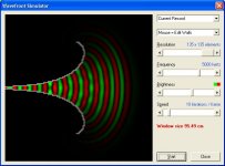
If I understand correctly, I think you might be trying to use the Wavefront Simulator for something more than it was designed for
. It simply shows how theoretical isophase wavefronts propagate down a horn towards an open mouth - that is all. In real life, things are more complicated than that.Kind regards,
David
Jmmlc said:What do you think if the logarithm of the displacment of the diaphragm logarithm was drawn?
Hi Jean-Michel,
Sorry, you will have to keep exporting your results
.Kind regards,
David
David McBean said:
If I understand correctly, I think you might be trying to use the Wavefront Simulator for something more than it was designed for
Hello,
If i tried to simulate something the software wasn't designed for, I will not have the desired result but I have the desired result ie a standing wave, which is not a propagate wavefront.
Or it's my reading of simulation that is not good.
With this simulation, I defined a standing wave with a center Stationary black area (0, node) surrounded by an alternating red (+, antinode) and green (-, antinode) area through the black (0).
I mean an alternating red>black>green>black>red>black>green...(+>0>->0>+>0>-...) with a (almost, depending of precision adjustment I think) stationnary position.
Re: Re: Re: Re: Re: Re: Re: HORNRESP VERSION 22.10
Hello David,
The question I raised, is quite independant on the ability of Hornresp to predict any frequency response at a given angle from the axis.
If, for a constant velocity source at throat, we compare BEM and Hornresp responses for different angles from axis, we can see that within an interval of frequency of 2 octaves above the frequency cut-off (illustrated case is for a Le Cleac'h horn having a cut-off of 425Hz, BEM simulations performed by Bjørn Kolbrek)Hornresp gives quite similar results until 40 degrees off axis.
The BEM simulations with a real compression driver show only a small difference with the constant velocity hypothesis.
When using the constant velocity hypothesis we allways obtain a rising on axial response of many horns (not only for the Le Cléac'h horn)
On the other hand we have dozens of axial response with the different drivers on Le Cléac'h horn or Kugelwellen horns or Tractrix horns... and they never show rising slope on-axis frequency response.
We have to explain why.
May be it is a question of distribution of pressure on the driver throat...
May be we have to question the constant velocity model used in the simulations...
Best regards from Paris, France
Jean-Michel Le Cléac'h
David McBean said:
Hi Jean-Michel,
Although the Hornresp directivity tools simulate the general characteristic behaviours of the different horn flare profiles reasonably well, the results are not necessarily 100 percent accurate in an absolute sense. Full FEM or BEM modelling will give more precise results, but at the expense of calculation times, as Bjørn Kolbrek has shown. Hornresp directivity results should be considered as indicative only.
Taking into account the above limitations in the Hornresp directivity model, is there still any value in adding the diaphragm constant acceleration option to the program?
Kind regards,
David
Attachments
thend said:If i tried to simulate something the software wasn't designed for, I will not have the desired result but I have the desired result ie a standing wave, which is not a propagate wavefront.
Hi thend,
Sorry, but I am not sure of the point you wish to make
.I assume you have some issue with the Hornresp Wavefront Simulator, but there is little I can do to change the way it operates.
Kind regards,
David
Re: Re: Re: Re: Re: Re: Re: Re: HORNRESP VERSION 22.10
Hi Jean-Michel,
The constant velocity diaphragm model is very straightforward, I wouldn't have thought that there could be too many problems with it.
Assuming the power response simulation is reasonably accurate, couldn't the rising on-axis pressure response prediction be due simply to Hornresp over-estimating "beaming" effects at higher frequencies - ie the actual beamwidth is not as narrow as that predicted by the program?
Would you still like a constant acceleration option to be added to Hornresp?
Kind regards,
David
Jmmlc said:May be we have to question the constant velocity model used in the simulations...
Hi Jean-Michel,
The constant velocity diaphragm model is very straightforward, I wouldn't have thought that there could be too many problems with it.
Assuming the power response simulation is reasonably accurate, couldn't the rising on-axis pressure response prediction be due simply to Hornresp over-estimating "beaming" effects at higher frequencies - ie the actual beamwidth is not as narrow as that predicted by the program?
Would you still like a constant acceleration option to be added to Hornresp?
Kind regards,
David

thend said:In this case, where is the propagate wavefront?
Hi thend,
It doesn't really matter - isophase wavefronts can be considered to be defined by either the red, green or black lines.
Hopefully the attached example will make things a bit clearer.
Kind regards,
David
Attachments
Greets!
DB,
FYI, after ~ a month I finally had to re-boot last night due to the virtual memory issue, so for whatever reason the 'problem' appears to be back to its normal cycle. Note that there's been various auto installed security updates during this time. Anyway, time to find out what the latest HR version may hold.
Thanks again for all your efforts.
GM
GM said:FYI, after ~ a month I finally had to re-boot last night due to the virtual memory issue, so for whatever reason the 'problem' appears to be back to its normal cycle. Note that there's been various auto installed security updates during this time.
Hi GM,
Thanks for the update. I think if Hornresp was the virtual memory culprit, then you would be re-booting far more often
.BTW, have you seen any more "Subscript out of range" errors?
Kind regards,
David
David McBean said:
Hi GM,
Thanks for the update. I think if Hornresp was the virtual memory culprit, then you would be re-booting far more often
BTW, have you seen any more "Subscript out of range" errors?
Kind regards,
David
Greets!
You're welcome!
No, in the last month I've had no error messages other than the normal warnings or noticed any glitches. Dunno, these problems came and went during a time when the only real changes going on with my computer AFAIK were HR updates. Ah well, just another one of life's little mysteries.
GM
Hi David_Web,
Sorry, I thought I had made that clear in my original reply (Post #618) - "The system volume is already included in the caption above the drawing shown in the Schematic Diagram view of the Tapped Horn Wizard."
So does my original response - "This my preferred location for the information."
Kind regards,
David
David_Web said:Tapped horn wizard does not show L in response. Only when showing schematic.
Sorry, I thought I had made that clear in my original reply (Post #618) - "The system volume is already included in the caption above the drawing shown in the Schematic Diagram view of the Tapped Horn Wizard."
David_Web said:So my request stands.
So does my original response - "This my preferred location for the information."
Kind regards,
David
GM said:No, in the last month I've had no error messages other than the normal warnings or noticed any glitches.
Hi GM,
Excellent news indeed - thank you. Perhaps one of the code changes I introduced solved the problem, although I have no idea why that should have made any difference
. As you say, just another one of life's little mysteries...Kind regards,
David
- Home
- Loudspeakers
- Subwoofers
- Hornresp