Thank you for explaining that in such an understandable way. The low frequency I was refering to was ~180hz and up, so there is definitely some directivity to speak of according to hornresp, and seeing as im using it for a midhorn this is extremely helpful information. Thanks again. ")
Hornresp and AkAbak Directivity Models
Hi Everyone,
From time to time I am asked via e-mail why the Hornresp pressure response chart results are not the same as those predicted by AkAbak. With activities being currently relatively quiet on the Hornresp front, I have taken the opportunity to study the AkAbak directivity models more closely, to better understand why there are such significant differences. The findings have proved to be most interesting...
The axisymmetric exponential horn used for the comparison tests has a throat diameter of 5/8 inches, a mouth diameter of 12 inches and an axial length of 18 inches. The test frequency is 4000 hertz.
The equivalent Hornresp input values are:
S1 = 1.98
S2 = 729.66
L12 (Exp) = 45.72
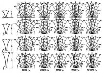
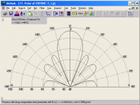
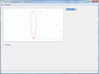
Attachment 1 shows the measured polar response for the test horn (second row from the top, third column from the left).
Attachment 2 shows the polar response calculated using a relatively sophisticated boundary element model, known to produce accurate predictions. The results took 22 seconds to generate on a 1.65 GHz 64-bit computer. As expected, the predicted polar response is similar to the measured response shown at the intersection of row 2 and column 3 in Attachment 1.
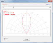
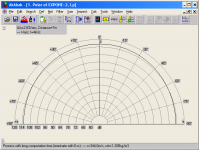
Attachment 3 shows the polar response calculated by Hornresp. It is quite similar to the responses shown in Attachments 1 and 2.
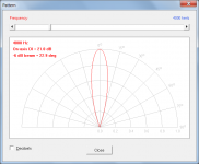
Attachment 4 shows the same Hornresp polar response, but displayed using a decibel scale to allow ready comparison to equivalent AkAbak results.
Attachment 5 shows the AkAbak polar response with the exponential horn modelled as a Waveguide element plus a Radiator element. The predicted response is quite different to the Attachment 4 response. The AkAbak pattern is only influenced by the size of the horn mouth and the frequency - the flare profile and length of the horn are not taken into account. Using this model, a conical horn will have exactly the same directivity characteristics as an exponential horn, which is clearly not the case in practice.
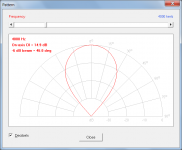
Attachment 6 shows the AkAbak polar response with the exponential horn modelled as a single Horn element. The predicted response is completely different to the Attachment 4 response, and therefore nothing like the measured response. The Horn element model assumes a notional "radiation cone", which means that the directivity characteristics are actually those of a conical horn somewhat smaller than the test exponential horn, which can lead to significant errors at higher frequencies.
For the chosen test example at least, the Hornresp directivity model would seem to be significantly more robust than the AkAbak model...
Kind regards,
David
Hi Everyone,
From time to time I am asked via e-mail why the Hornresp pressure response chart results are not the same as those predicted by AkAbak. With activities being currently relatively quiet on the Hornresp front, I have taken the opportunity to study the AkAbak directivity models more closely, to better understand why there are such significant differences. The findings have proved to be most interesting...
The axisymmetric exponential horn used for the comparison tests has a throat diameter of 5/8 inches, a mouth diameter of 12 inches and an axial length of 18 inches. The test frequency is 4000 hertz.
The equivalent Hornresp input values are:
S1 = 1.98
S2 = 729.66
L12 (Exp) = 45.72
Attachment 1 shows the measured polar response for the test horn (second row from the top, third column from the left).
Attachment 2 shows the polar response calculated using a relatively sophisticated boundary element model, known to produce accurate predictions. The results took 22 seconds to generate on a 1.65 GHz 64-bit computer. As expected, the predicted polar response is similar to the measured response shown at the intersection of row 2 and column 3 in Attachment 1.
Attachment 3 shows the polar response calculated by Hornresp. It is quite similar to the responses shown in Attachments 1 and 2.
Attachment 4 shows the same Hornresp polar response, but displayed using a decibel scale to allow ready comparison to equivalent AkAbak results.
Attachment 5 shows the AkAbak polar response with the exponential horn modelled as a Waveguide element plus a Radiator element. The predicted response is quite different to the Attachment 4 response. The AkAbak pattern is only influenced by the size of the horn mouth and the frequency - the flare profile and length of the horn are not taken into account. Using this model, a conical horn will have exactly the same directivity characteristics as an exponential horn, which is clearly not the case in practice.
Attachment 6 shows the AkAbak polar response with the exponential horn modelled as a single Horn element. The predicted response is completely different to the Attachment 4 response, and therefore nothing like the measured response. The Horn element model assumes a notional "radiation cone", which means that the directivity characteristics are actually those of a conical horn somewhat smaller than the test exponential horn, which can lead to significant errors at higher frequencies.
For the chosen test example at least, the Hornresp directivity model would seem to be significantly more robust than the AkAbak model...
Kind regards,
David
Attachments
Last edited:
@nanonymous
Try to sim it like this:
In tools: Select Rear-Chamber-> ported
in the lower left section, enter volume of the enclosure and depth of it
in the middle lower, you put the geometrie of the port
right/low you put zero/null
In the horn section: Put the front baffle dimension and a depth of the horn of 1cm.... This way you get an idea of what the front wall does to the upper frequencies (the bigger the box, the lower the effect goes..).
See the help file for further stuff on the matter
For the chosen test example at least, the Hornresp directivity model would seem to be significantly more robust than the AkAbak model...
^2
Been saying this for a few years now.
AkaBak is officially eating Hornresp's dust.
Is that situation the same with parabolic horns?
Hi BP1Fanatic,
AkAbak cannot directly simulate a parabolic horn - it can only approximate one using multiple conical elements.
Because of the multiple flare profiles involved when multiple elements are specified, the accuracy of the directivity response calculated using a relatively simple model such as that provided in AkAbak, becomes questionable to say the least. This is why the Hornresp directivity tools are disabled for multiple-segment horns. The only way to get an accurate prediction would be to use a full finite element model similar to the boundary element model referred to in my previous post.
While I do not have any actual measurements to compare with, the Hornresp polar response predictions for a single-segment parabolic horn are believed to be reasonably accurate.
This can be tested to some degree by using the same horn dimensions as in my previous post, but with the flare changed from exponential to parabolic:
S1 = 1.98
S2 = 729.66
L12 (Par) = 45.72
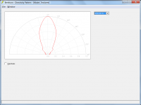
Attachment 1 shows the polar response calculated using the same boundary element model as before, known to produce accurate predictions. The results took 26 seconds to generate.
Attachment 2 shows the polar response calculated by Hornresp. It is very similar to the response shown in Attachment 1.
Kind regards,
David
Attachments
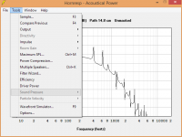
I’m trying to simulate a vented subwoofer with Hornresp and I’m interested in the port velocity. Somehow I cannot select particle velocity in the Tool Menu though. What am I doing wrong?
Hi nanonymous,
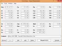
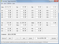
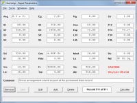
It is better to simulate your vented subwoofer as shown in the attached screenprint. The vent is then treated as a true port tube, with the inlet end correction being taken into account.
With your method, the port tube is treated as a conventional cylindrical horn, without the necessary throat end correction.
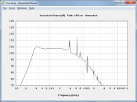
Select Tools > Output > Port from the Acoustical Power window, and then select Tools > Particle Velocity > Port Inlet / Port Outlet.
Kind regards,
David
Attachments
AkaBak is officially eating Hornresp's dust.
Hi Mark,
Don't be too hasty in your judgement
.As I have said before, AkAbak is excellent for modelling complex designs, which is why there is an AkAbak script export feature in Hornresp.
The two programs complement each other very nicely indeed.
Kind regards,
David
The difference seems to be that D.McBean supports Hornresp and reacts to reports when anything is found to be wrong or misleading.
Can the same be said of Akabak?
How long has the reported error highlighted in post5122 existed?
Will Akabak correct their software to remove the (known) error?
Can the same be said of Akabak?
How long has the reported error highlighted in post5122 existed?
Will Akabak correct their software to remove the (known) error?
Will Akabak correct their software to remove the (known) error?
Products Akabak:
AkAbak is getting on in years. From the the first version more than 17 years have passed. The current AkAbak has the version-number 2.1 and is a 16bit compilation, which needs a special environment to run. The application makes use of filenames, which are formatted in the old "8.3"-DOS format.
I believe it is unlikely that they are supporting it anymore.
Last modified date of the program is 2008-02-16.
Not quite right guys, akabak has moved on to Abec3 which is akabak combined with BEM for radiation, imho by far the most powerfull FREE tool out there.
Abec 3
This is great!
Have you tried it kessito? Is the input format compatible with Akabak?
It is better to simulate your vented subwoofer as shown in the attached screenprint.
I forgot to mention that to maintain the same relative positions of the outputs, the path length difference would need to be changed
from 14.8 cm to -14.8 cm. Also, the result will be slightly different to the previous one due to the end correction now being taken into account - see attachment.
Attachments
Last edited:
Yes,I use it and it's extremely powerfull. The lem scripts are fully compatible with akabak, without the 16 bit restrictions from akabak.
David is awesome with hornresp, but joerg pfanzer who develops akabak/ABEC For free is also awesome. I really have much respect for guys like these who put that much effort in providing very good and free tools to the community.
I am very happy with Hornresp and especially happy that you are so supportive of the DIY community David With that said I would like to nit-pick a little in the hope of further improving Hornresp.
Bug:
It seems that the number of drivers set by "driver arrangement" is not stored when saving a model. If I design a construction using multiple drivers I have to remember to re-enter the correct number of drivers each time the model is loaded.
Feature request:
It would be nice if the stored settings for number of drivers was displayed when opening the 'driver arrangement' dialog box instead of defaulting to 1 driver, no isobaric. The driver location is the only thing that seems to be remembered.
I am guessing that these two annoyances are just two manifestations of the same issue.
I mainly use Hornresp through Wine on Mac OS X and Linux but the issue was also present when running on my friends Windows box.
With that said I would like to nit-pick a little in the hope of further improving Hornresp.Bug:
It seems that the number of drivers set by "driver arrangement" is not stored when saving a model. If I design a construction using multiple drivers I have to remember to re-enter the correct number of drivers each time the model is loaded.
Feature request:
It would be nice if the stored settings for number of drivers was displayed when opening the 'driver arrangement' dialog box instead of defaulting to 1 driver, no isobaric. The driver location is the only thing that seems to be remembered.
I am guessing that these two annoyances are just two manifestations of the same issue.
I mainly use Hornresp through Wine on Mac OS X and Linux but the issue was also present when running on my friends Windows box.
Hi minkuni,
The driver arrangement should definitely be stored as part of the permanent data record when a model is saved, as illustrated in the attached screenprint. What version of Hornresp are you using?
* Does anyone else have a problem similar to that currently being experienced by minkuni?
While it could certainly be done, the existing functionality makes it easier to reset to a single driver - which is why it was adopted. Normally the Driver Arrangement tool is only selected when a change is to be made, so it shouldn't really matter if the settings reflect the currently-specified configuration or not.
While I personally prefer the tool to open with "a clean slate", I would be prepared to consider making the suggested change if others also feel that it would be an improvement - bearing in mind that the 'quick single driver reset' feature would then be lost .
Kind regards,
David
It seems that the number of drivers set by "driver arrangement" is not stored when saving a model.
The driver arrangement should definitely be stored as part of the permanent data record when a model is saved, as illustrated in the attached screenprint. What version of Hornresp are you using?
* Does anyone else have a problem similar to that currently being experienced by minkuni?
It would be nice if the stored settings for number of drivers was displayed when opening the 'driver arrangement' dialog box instead of defaulting to 1 driver, no isobaric.
While it could certainly be done, the existing functionality makes it easier to reset to a single driver - which is why it was adopted. Normally the Driver Arrangement tool is only selected when a change is to be made, so it shouldn't really matter if the settings reflect the currently-specified configuration or not.
While I personally prefer the tool to open with "a clean slate", I would be prepared to consider making the suggested change if others also feel that it would be an improvement - bearing in mind that the 'quick single driver reset' feature would then be lost .
Kind regards,
David
Attachments
- Home
- Loudspeakers
- Subwoofers
- Hornresp