Hello Michael,
We don't need CSD in order to know how to equalize a driver+horn.
There is so many artifcats in the CSD (waterfal) you show that happy are those who can interpret it!
See the attached schematics I drawn.
On top the same FFT window with a small apodizing time (in black) and a large apodizing time (in red).
Then the 2 graphs on the bottom represent a single frequency line from a CSD., the first one on a series of equal level pulses separated by a delay equal to the width of the FFT (for an easier demonstration). The second one is for a series of decreasing level pulses. With the small value of the apodizing time we have flat tops and steps appearing, they are artifact. For sure a specialist will correctly interpret them but if we look for a definition of common requirements for CSD (or wavelets...) parametering we have to look for something more universal. As you can see the large apodizing time leads to a better representation of the phenomenon we study.
I disagree with Elias about the need to favor time over frequency. For me it is easy to ear a 1000Hz frequency but it is impossible to say "this duration is 1ms".
Best regards from Paris, France
Jean-Michel Le Cléac'h
FR at t=0 is hell of a difference to after occurring massive reflection.
This is simply so as comb filtering does not happen *before* first delay time.
The consequence I see is that we will have hard times to equalize such a horn –...
Also – this same mis-behaviour / mis – consistency in time is repeated on every room reflection again !
Attachments

Hello EarlK,
Here is in attached file a CSD I obtained using Arta on the .pir file of the JBL2431H on a RCA MI9594.
What is noticeable is the long resonance (may be due to a reflection) between 7 and 8kHz.
Also noticeable is the group delay rise below 1.8kHz which is interpretable as the effect of "strong" reflections after 0.8ms and 1,3ms.
Best regards from Paris, France
The driver is the JBL 2431H & the horn is a small 60 by 40 waveguide ( I can't remember the model # off-hand ).
Here are 2 ARTA files ( zipped ) for those who want to slice & dice this data a bit more .
Attachments

I did some listening tests to the 511 vs Dayton horn vs Dayton 12" round WG.
They all sound different - and for the most part sound just like they look.
Here is a completely subjective list.
The two plastic horns sound like plastic, but the metal 511 sounds more woody. Strange. I can see why the round waveguides would be popular. Especially above 1-2Khz. A very direct sound. But maybe too direct for my tests. None of them disappear completely.
Sorry I will not be able to publish results soon. Too much work for the next week. May have some files for you next Wednesday.
They all sound different - and for the most part sound just like they look.
Here is a completely subjective list.
- The 12" round WG sounds very clear, very immediate. No honk, some glare. This WG is shallow, and sounds like it. It gives a feeling of almost listening to the driver alone.
- 12" Dayton horn. Less direct, more subtle. Maybe more colored. The horn is deeper and sounds like it.
- Altec 511. Darker, with some honk. Very much a midrange honk when it's there. "Guttural", as has been said before. But also seems to carry more ambient detail, can hear more reverb in the recording
The two plastic horns sound like plastic, but the metal 511 sounds more woody. Strange. I can see why the round waveguides would be popular. Especially above 1-2Khz. A very direct sound. But maybe too direct for my tests. None of them disappear completely.
Sorry I will not be able to publish results soon. Too much work for the next week. May have some files for you next Wednesday.
Hello ZilchLab,
Cool, I found 2 OS waveguide IR files posted there named as:
waveguide_00.txt
waveguide.txt
But I couldn't find info is it with foam or without?
Also there was some JBL files:
jbl_00.txt
jblh_00.txt
Have to see what they contain..
- Elias
Cool, I found 2 OS waveguide IR files posted there named as:
waveguide_00.txt
waveguide.txt
But I couldn't find info is it with foam or without?
Also there was some JBL files:
jbl_00.txt
jblh_00.txt
Have to see what they contain..
- Elias
Geddes posted some in the Horn vs. Waveguide thread, early pages. You'll see everyone doing their favorite analyses of them there....
Hello,
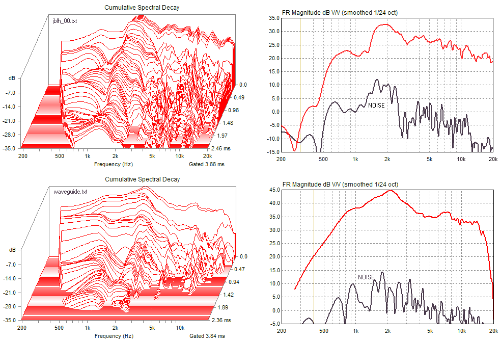
Here is the direct link to the JBL_00.txt file mentionned by Elias:
http://www.diyaudio.com/forums/attachments/multi-way/108687d1211410404-horn-vs-waveguide-jbl_00.txt
Here is attached the CSD I obtained using ARTA. (really ugly!)
Best regards from Paris, France
Jean-Michel Le Cléac'h
Here is the direct link to the JBL_00.txt file mentionned by Elias:
http://www.diyaudio.com/forums/attachments/multi-way/108687d1211410404-horn-vs-waveguide-jbl_00.txt
Here is attached the CSD I obtained using ARTA. (really ugly!)
Best regards from Paris, France
Jean-Michel Le Cléac'h
Cool, I found 2 OS waveguide IR files posted there named as:
waveguide_00.txt
Have to see what they contain..
- Elias
Attachments

Last edited:
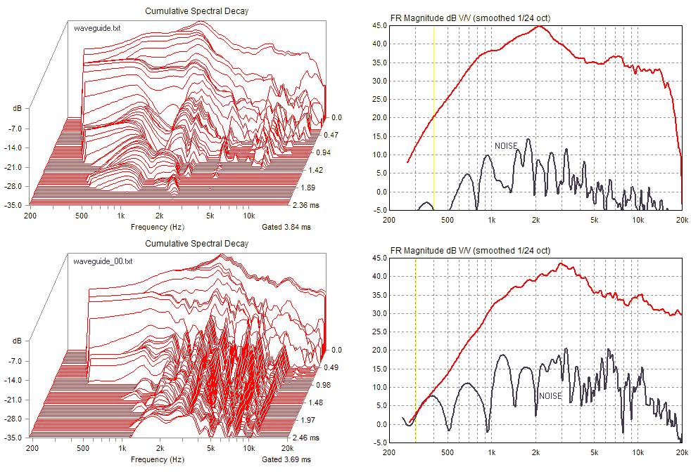
Hello,
Here is attached the CSDs of the waveguide_00.txt file (left) and of the waveguide.txt file (right) I obtained using ARTA.
Direct link to file waveguide_00.txt is:
http://www.diyaudio.com/forums/atta...1211410323-horn-vs-waveguide-waveguide_00.txt
Best regards from Paris, France
Jean-Michel Le Cléac'h
Attachments


Last edited:
Hello
I should mention the analysis done by Melavi on the JBL and Waveguide files previously mentionned.
http://www.diyaudio.com/forums/multi-way/123426-horn-vs-waveguide-21.html#post1518695
and the one performed by Jzagaja:
http://www.diyaudio.com/forums/atta...1617551-horn-vs-waveguide-untitled-1-copy.gif
http://www.diyaudio.com/forums/atta...1577371-horn-vs-waveguide-untitled-1-copy.gif
Best regards from Paris, France
Jean-Michel Le Cléac'h
Last edited:
Yes, a pleasant coloration, no?... but the metal 511 sounds more woody. Strange.
[I was tempted to call it "nutty," instead, but knew somehow that might be inherently dangerous.
]I have always assumed Geddes with foam, and JBL without.But I couldn't find info is it with foam or without?
[Ask him, maybe....
]
Last edited:
It's nice to see Melavi also uses wavelets!

I should mention the analysis done by Melavi on the JBL and Waveguide files previously mentionned.
http://www.diyaudio.com/forums/multi-way/123426-horn-vs-waveguide-21.html#post1518695
We don't need CSD in order to know how to equalize a driver+horn.
yes and no
I actually have chosen that plot because its a "measurement" that shows very intuitively what I want to make the point – just go with the obvious pattern and *do not* dig into the details.
I could have taken other pix from this thread as well - as what I want to draw anybody's attention to, is basically independent from the EV ST350 and even independent if the reflections seen there are from the horn or from the room.
The point that matters when we are discussing that part of horn honk that is related to reflections due to sub-optimal diffraction alignment is, that we are investigating in the simple yet tricky issue of comb filtering – but seem to forget that there is a brick wall discontinuity involved here – the delay time of reflection.


Seen above constructive and destructive summation (as parallel of delayed reflections).
There was a good discussion several times, about how to look at such delayed effects in the light of EQ'ing - back in Lynn's thread and elsewhere – mainly with John Kreskovsky.
It was vastly concluded, that such comb filtering can be seen as a linear phenomena and thus to be seen as being min phase for any given mic and listening position – so that it *is* accessible to EQ'ing.
I agree that the steady state *after* the reflection delay time can be EQ'ed perfectly - but I highly doubt that anyone is capable to EQ comb filter effects correctly *from t=0*
Thus IR *must* be compromised by that facet of horn honk.
This is a paramount difference - not often outspoken clearly.
Hence I wrote about the difference in EQ'ing needs for the time until comb filtering actually happens first (the delay time window) and about the time after....
Above probably is "no big deal" for 180deg included dipole horns (open baffle that is
) where wave length is mostly above reflection time delay – but certainly "comb filter honk" is no small issue for usual horns where reflection-time-delay is usually several wave lengths.Bottom line - one would yet have to show me that this horn honk specific comb filtering issue can be considered to be min phase behaviour *from T=0 to T=infinity* - before I agree to look at frequency wiggles as to be the *dominant* issue ....
Michael
Last edited:
Hello,
To try to minimize reflections, Homs, effects of diffraction in horns just using a minimum phase approach is IMHO a simplistic view and a dead end issue.
Eventually a DSP could be used to perform a pre-correction of the signal...
Best regards from Paris, France
Jean-Michel Le Cléac'h
To try to minimize reflections, Homs, effects of diffraction in horns just using a minimum phase approach is IMHO a simplistic view and a dead end issue.
Eventually a DSP could be used to perform a pre-correction of the signal...
Best regards from Paris, France
Jean-Michel Le Cléac'h
There was a good discussion several times, about how to look at such delayed effects in the light of EQ'ing - back in Lynn's thread and elsewhere – mainly with John Kreskovsky.
It was vastly concluded, that such comb filtering can be seen as a linear phenomena and thus to be seen as being min phase for any given mic and listening position – so that it *is* accessible to EQ'ing.
I agree that the steady state *after* the reflection delay time can be EQ'ed perfectly - but I highly doubt that anyone is capable to EQ comb filter effects correctly *from t=0*
Thus IR *must* be compromised by that facet of horn honk.
...
but certainly "comb filter honk" is no small issue for usual horns where reflection-time-delay is usually several wave lengths.
Sure - I know ! - I didn't aim it to your contour nor work
- just to outline the obvious in the context of the thread...
Hope you don't mind ?
DSP BTW does not help here either - the *only* medicine is avoiding strong / discrete reflection by optimizing diffraction alignment - or - dampen this reflections down as is done with transmission line (and similar) speakers...
Michael
Last edited:
One consequence of what I brought up is, that Fourier analysis on such issues might not exactly be the best idea - simply as time invariance exactly in the interval we are most interested in for those "comb filter honk" is not a given.
Being no "math head" - as you know - I easily could be wrong of course...
So I'd like to have that wavelet analysis available - simply for comparison and being able to chose what I think visualizes best when I "press buttons" (stupid monkey I am )...
Michael
Being no "math head" - as you know - I easily could be wrong of course...
So I'd like to have that wavelet analysis available - simply for comparison and being able to chose what I think visualizes best when I "press buttons" (stupid monkey I am
)...Michael
Last edited:
See the attached schematics I drawn.
On top the same FFT window with a small apodizing time (in black) and a large apodizing time (in red).
Then the 2 graphs on the bottom represent a single frequency line from a CSD., the first one on a series of equal level pulses separated by a delay equal to the width of the FFT (for an easier demonstration). The second one is for a series of decreasing level pulses. With the small value of the apodizing time we have flat tops and steps appearing, they are artifact. For sure a specialist will correctly interpret them but if we look for a definition of common requirements for CSD (or wavelets...) parametering we have to look for something more universal. As you can see the large apodizing time leads to a better representation of the phenomenon we study.
Jean-Michael, Pano, all, I upgraded to ARTA 1.6.1 and do not get the same CSD results as previously - what revision of ARTA do you use ?
Michael
Last edited:
Horn Honk $$ WANTED $$
Michael ,
- I'll continue to post here because I'm determined to win this cash reward which you've so generously promised in the threads' title .
- How much ( btw ) is the prize worth ?

<> EarlK
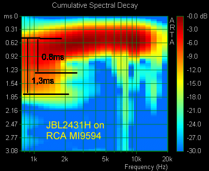

ps 1 ; The RCA MI9594 ( I posted the zipped, .pir file last page ) should clearly be in the lead at this point / excepting that I now see the rules are somewhat vague for claiming victory .


ps 2 ; I'm using ARTA 1.6.1 and I can not make my CSDs look like JMs / but then , I figure it's my lack of experience with CSDs .
Michael ,
- I'll continue to post here because I'm determined to win this cash reward which you've so generously promised in the threads' title .
- How much ( btw ) is the prize worth ?
<> EarlK
ps 1 ; The RCA MI9594 ( I posted the zipped, .pir file last page ) should clearly be in the lead at this point / excepting that I now see the rules are somewhat vague for claiming victory .
ps 2 ; I'm using ARTA 1.6.1 and I can not make my CSDs look like JMs / but then , I figure it's my lack of experience with CSDs .
Last edited:
Hello EarlK
If you are talking about your posted plot it looks like you are not gating before the pulse or after your first room reflection. You also are using a different dB scale for the decay. Try to match his period for the measurement and decay scale and see what happens. Hope this helps.
Rob
I'm using ARTA 1.6.1 and I can not make my CSDs look like JMs / but then , I figure it's my lack of experience with CSDs .
If you are talking about your posted plot it looks like you are not gating before the pulse or after your first room reflection. You also are using a different dB scale for the decay. Try to match his period for the measurement and decay scale and see what happens. Hope this helps.
Rob
- Status
- This old topic is closed. If you want to reopen this topic, contact a moderator using the "Report Post" button.
- Home
- Loudspeakers
- Multi-Way
- Horn Honk $$ WANTED $$