Greetings from FixitLand!
I am unclear on this...you have a PCB layout, but is this amp built point-to-point at the moment? Could we please see a photo of the circuit as you've built it? We have the schematic; I mean the actual, physical circuit. That would help us troubleshoot what you have built up to now. Please do this before worrying about a new PCB layout. Once you have a working point-to-point circuit, you can use that to (re-)design a printed circuit board. (Personally, I don't care much for PCBs in tube circuits.)
Your power supply drawing (DSC00055.jpg) shows two 470-uF 200V caps in series following the rectifier, and two 330-uF 200V caps in series following a 100-ohm 15W resistor. I would recommend replacing each of these pairs with 400-volt single electrolytics of between 100 and 220 uF each. The junction of each pair of electrolytics you have now will not necessarily be at half the DC supply voltages. Alternatively, strap a 220K resistor across each electrolytic, so as to equalize the voltages across each cap.
As was noted, the ECC82 (a k a 12AU7) needs pins 4 and 5 strapped to one side of the 6.3-volt heater supply, and pin 9 connected to the other. It's a 12.6-volt, center-tapped heater that can be run on 12.6 or 6.3 V. But 6.3 V across pins 4 and 5 will run the heater at only half voltage. On your power transformer, you show two 6.3-volt windings, one of them center-tapped. Or is that one 6.3-volt (the 3A rated one), and one 12.6-volt center-tapped (the 300mA rated one)? The labeling is unclear.
I have no complaint with your output transformer. The 0.027-uF (27 nF) coupling capacitors into the output tubes seem low (0.1 uF or 100 nF is better) but that's not the problem here either. The EL84s' cathode resistor (120 ohm) seems low to me; would probably go to 220 or 250. But there's really nothing in this schematic that should be the problem. So we need to see exactly how you've physically built your rig.
In regards your PCB layout: Is this as seen from the top (component side) or the bottom (wiring side)? The tube socket numbering suggests it's the top side. If it's intended to be the wiring side, the tube sockets are numbered backwards. That has nothing to do with your point-to-point-wired setup, unless that too is wired wrong. You said the heaters light off, so that seems unlikely.
Looking forward to seeing your work.
Take care,
--
J. E. Knox "The Victor Freak"
Connecting a current meter into the cathode circuit necessarily involves changing the circuit. That is why we usually measure voltages and calculate current. Otherwise it is easy to accidentally hide the fault.
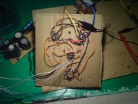
I can't see any grid stoppers in the 'cardboard' circuit. I can see long wires. RF oscillation is a possibility. I can't see any proper heater wiring. I would expect this layout to do strange things. You can't expect a lash-up like that to behave properly; you might be lucky, you might be unlucky.
I can't see any grid stoppers in the 'cardboard' circuit. I can see long wires. RF oscillation is a possibility. I can't see any proper heater wiring. I would expect this layout to do strange things. You can't expect a lash-up like that to behave properly; you might be lucky, you might be unlucky.
Personally I would have had the corrugated cardboard rotated 90 degrees for strength, but hey that's just me............")
Rojoknox - I think this resistor is carrying current for two EL84's hence it is about half the normal value.
The EL84s' cathode resistor (120 ohm) seems low to me; would probably go to 220 or 250.
Rojoknox - I think this resistor is carrying current for two EL84's hence it is about half the normal value.
Last edited:
Greetings from FixitLand!
Definitely don't give up. Even built on a piece of cardboard, this circuit should work to some level.
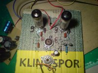
Looking at DSC00056.jpg...on the leftmost EL84 there's an orange wire from pin 3 (cathode) to a circuit point farther down the "board" (appears to be the 120-ohm cathode resistor), along with a short black wire going to a clip lead, but on the rightmost EL84 there's a yellow wire going *somewhere*. The schematic shows the two pin-3s connected together. Where is that yellow wire going? (Part of a test setup? The short black wire *looks* like it could have been connected to the rightmost EL84's pin 3.)
Is something connected to pin 9 of the EF86?
Best thing at the moment is to go over the circuit as built and double-check each connection and part value against the schematic.
Re the 120-ohm cathode resistor...The GE datasheet calls for 130 ohms on a push-pull pair. My bad on that; I was mentally short-circuiting to a typical value for 6V6s. When I built my EL84 amp, I used fixed bias. Whatta I know?! <grin>
Take care,
--
J. E. Knox "The Victor Freak"
Definitely don't give up. Even built on a piece of cardboard, this circuit should work to some level.
Looking at DSC00056.jpg...on the leftmost EL84 there's an orange wire from pin 3 (cathode) to a circuit point farther down the "board" (appears to be the 120-ohm cathode resistor), along with a short black wire going to a clip lead, but on the rightmost EL84 there's a yellow wire going *somewhere*. The schematic shows the two pin-3s connected together. Where is that yellow wire going? (Part of a test setup? The short black wire *looks* like it could have been connected to the rightmost EL84's pin 3.)
Is something connected to pin 9 of the EF86?
Best thing at the moment is to go over the circuit as built and double-check each connection and part value against the schematic.
Re the 120-ohm cathode resistor...The GE datasheet calls for 130 ohms on a push-pull pair. My bad on that; I was mentally short-circuiting to a typical value for 6V6s. When I built my EL84 amp, I used fixed bias. Whatta I know?! <grin>
Take care,
--
J. E. Knox "The Victor Freak"
Greetings from FixitLand!
Definitely don't give up. Even built on a piece of cardboard, this circuit should work to some level.
Looking at DSC00056.jpg...on the leftmost EL84 there's an orange wire from pin 3 (cathode) to a circuit point farther down the "board" (appears to be the 120-ohm cathode resistor), along with a short black wire going to a clip lead, but on the rightmost EL84 there's a yellow wire going *somewhere*. The schematic shows the two pin-3s connected together. Where is that yellow wire going? (Part of a test setup? The short black wire *looks* like it could have been connected to the rightmost EL84's pin 3.)
Is something connected to pin 9 of the EF86?
Best thing at the moment is to go over the circuit as built and double-check each connection and part value against the schematic.
Re the 120-ohm cathode resistor...The GE datasheet calls for 130 ohms on a push-pull pair. My bad on that; I was mentally short-circuiting to a typical value for 6V6s. When I built my EL84 amp, I used fixed bias. Whatta I know?! <grin>
Take care,
--
J. E. Knox "The Victor Freak"
Yes, the two pin 3-s are connected together, i just measured the current with my multimeter. EF86's pin 9 is not connected.
Greetings from FixitLand!
The different voltage and current readings may have been a result of the multimeter connections. With the pin-3 tie wire reconnected, what is the voltage across the 120-ohm resistor?
"EF86's pin 9 is not connected." That is the control-grid terminal. If that's not connected, you have no input! Also, the tube is running without bias, so it will behave unpredictably (can float either to cutoff or to saturation).
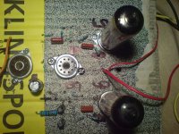
In the photos I notice you have only the two EL84s plugged in. That's fine at the moment. In that state, do you hear hum when touching one of the EL84 grids (pin 2) and silence otherwise?
Take care,
--
J. E. Knox "The Victor Freak"
The different voltage and current readings may have been a result of the multimeter connections. With the pin-3 tie wire reconnected, what is the voltage across the 120-ohm resistor?
"EF86's pin 9 is not connected." That is the control-grid terminal. If that's not connected, you have no input! Also, the tube is running without bias, so it will behave unpredictably (can float either to cutoff or to saturation).
In the photos I notice you have only the two EL84s plugged in. That's fine at the moment. In that state, do you hear hum when touching one of the EL84 grids (pin 2) and silence otherwise?
Take care,
--
J. E. Knox "The Victor Freak"
Greetings from FixitLand!
"...I removed that [input signal] after I removed the EF86 tube."
OKeh, that's fine. We'll concentrate first on the output stage, then work backwards. What do you find with the "touch-pin-2" test? Have you a voltage measurement across the 120-ohm cathode resistor?
Take care,
--
J. E. Knox "The Victor Freak"
Greetings from FixitLand!
Only a buzz, no silence. 50-100 Hz, that means a power-supply issue or grounding problem. Is that buzz really REALLY loud, or more a background noise? Try this now: Ground pin 2 of both of the EL84s. That should silence the hum if it's just grounding. If you still hear the hum/buzz, you've got a power-supply issue. It's possible the pin-2-grounding trick will reduce but not entirely eliminate the hum.
Take care,
--
J. E. Knox "The Victor Freak"
- Status
- This old topic is closed. If you want to reopen this topic, contact a moderator using the "Report Post" button.
- Home
- Amplifiers
- Tubes / Valves
- Homemade EL84 Push-Pull amp doesn't work