ECC82 heaters should be wired in parallel for 6.3V operation, not series. Connect 4 & 5 together and connect to one side of filament supply, wire pin 9 to other side of filament supply.
Check that you correctly identified all electrode pin numbers on schematic and in your build.
Recheck that you have not wired any sockets backwards which I admit to my embarrassment is something I have done, and more than once..
Check that you correctly identified all electrode pin numbers on schematic and in your build.
Recheck that you have not wired any sockets backwards which I admit to my embarrassment is something I have done, and more than once..
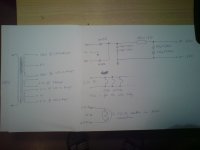
The amp PCB looks a bit cramped. Remember that valves get hot and use high voltages. A bit of space benefits both. Grid stoppers should be close to the grid pin. I would not run tracks between valve pins unless absolutely necessary.
Your grounding scheme looks a bit random, with the input stage cathode circuit getting mixed up with the output stage grid circuit. That probably won't cause the current problem with buzz, but it is asking for future stability problems. Remember: every trace, every wire is a low value resistor not a short.
The PSU may need voltage-sharing resistors across the series capacitors, although there is a school of thought which says these are unnecessary as the caps adjust themselves.
The PSU may need voltage-sharing resistors across the series capacitors, although there is a school of thought which says these are unnecessary as the caps adjust themselves.
Agreed - the school of "real-world experience" (tm) says to put something like 220K across each of those two caps (power rating as required). The actual value is not critical but they should be the same. Two apparently identical capacitors can have significantly different values which will upset the voltage distribution if resistors are not fitted.
Further, the resistors will always provide a discharge path for voltage allowing approx 5 times R times C seconds from when you unplug the device before putting your fingers anywhere near.
Yes, something is wrong. You are solving the wrong problem. Bad hum in an output stage cannot be caused by AC heaters unless they are wired incorrectly. Using DC will, at best, hide the wiring problem. You really must forget about DC heaters for now and find the real fault. Later on, if you still have a tiny residual him from the heaters and can't learn how to twist wires properly then convert to DC.
It might be better to persist for a while with the point-to-point version. The reason is that if the mistake is due to a misconception on your part then the PCB will probably include that misconception and then be harder to correct. For example, you have misread the EL84 pinout.
+1,
At a later stage when you've ironed out your fault(s) you might want to hear what some of the more modern designs offered by the good people here sound like. A couple of ECC83's, some passives followed by a rewiring and you can enjoy a different amp design.
Last edited:
Yes but... I'm a little sad. I built so many amplifiers, TDA2003, 2030, 2050, 2822, 7294, even a JLH Class A 10W, and a Hiraga Le Monstre Class A 8W. These amplifiers work fine, i'm listening to the Hiraga right now. I think i need to correct my errors step by step. I checking the amplifier right now. I didn't misunderstand the EL84 pinout, because the heaters are working.
Alright, i think i need a fresh start.
OK, I see you only joined today so welcome to the forum.
- Status
- This old topic is closed. If you want to reopen this topic, contact a moderator using the "Report Post" button.
- Home
- Amplifiers
- Tubes / Valves
- Homemade EL84 Push-Pull amp doesn't work