More on my project.
I did the driver for one channel only employing 5 dual triodes. The first (12AU7) and second (12AX7), are the cross coupled phase spliter. The last is "cascoded" whit the 3rd stage, another 12AX7, the load is a series of two 68K resistors. DC coupled to the 4th, a WCF made of 2 12AU7). From there, I go to EL34 grids via a 1uF cap., and from the WCF is bootstrapped to the joint of two plate load resistors. This make in real circuit (measured with audio gen and oscilloscope) an overall gain of 121 times (from 1 grid to 1 out), and a frequency width of almost 85KHz, the higher signal from my generator. Its supply is only +240V (actively regulated with a linear tube regulator made with a 6DE7 and a 6CG7, all vertical sweep tubes), at the 2nd grid cascode triode there is about only 80V stabilized with a neon lamp, and with a peak excursion of 85V after top cutting the wave, it responds from about 1.3Hz with the capacitors I used. I can post the circuit in plain text in DOS ASCII char´s from MS EDIT.COM in CP437.
Opinions of this, suggestions are welcomed.
Last edited:
Hi Osvaldo,
Why not download LTspice which you can also use for analysis by adding the required tube libraries (if you want) to create a comprehensible schematic that you can upload here. Use a screen capture tool to create a jpg you can post here.
The other option would be to draw out the schematic by hand and carefully photograph it with your digital camera.
Posting using ascii characters makes it very difficult for most of us to understand. (There's no real reason to do this today)
The main advantage of toroid transformer is that you can make almost any core in small quantity for reasonable price, and you don't need a corresponding bobbin for winding.
1. The curve I've posted obtained from custom made O-core 160 mm outer diam.
2. Your key point is to have reasonable price for a custom core.
You've missed my point:
to spend some more and have core made from most suitable material
SE:
gap purpose is two fold - to allow DC bias - to put the core into linear region of B-H herewith linearizing the latter.
For STEEL it's 0.6..0.9T Bo + 0.4T of headroom.
Center tapped push-pull:
you need linear B-H from zero up*.
Low" (1000-4000) permeability nanocrystalline core has exactly that, having headroom at very least as big as SE has
----------------------------------------------------------------------------------------------------------------------------------------------------
*It's no the value of excitation current but rather it's shape. That said super-alloys with narrowest hysteresis curve (read magnetization current) give long, slow decaying harmonics' "tail". Modern thingies allow to have gap kind of behaviour without the gap present, particularly at zero or near zero bias.
ANY Iron/Steel has two kinks @ low to medium and @ medium to high excitation transition points - so the most distortions you'll get at low power, assuming the DC balance is perfect. Moreover offset will drift over time thus changing shape of harmonics "tail".
Last edited:
There is a fact that I hate windows, at my hpme I have only AMD486 running pure DOS v 7.10, and OrCAD, Microcap4, autotrax and any other DOS works fine yet, so I will not migrate for windows never!!!. Again, I HATE IT!!!Hi Osvaldo,
Why not download LTspice which you can also use for analysis by adding the required tube libraries (if you want) to create a comprehensible schematic that you can upload here. Use a screen capture tool to create a jpg you can post here.
The other option would be to draw out the schematic by hand and carefully photograph it with your digital camera.
Posting using ascii characters makes it very difficult for most of us to understand. (There's no real reason to do this today)
There is a fact that I hate windows, at my hpme I have only AMD486 running pure DOS v 7.10, and OrCAD, Microcap4, autotrax and any other DOS works fine yet, so I will not migrate for windows never!!!. Again, I HATE IT!!!
What do you use for browsing the web, then?
There is a fact that I hate windows, at my hpme I have only AMD486 running pure DOS v 7.10, and OrCAD, Microcap4, autotrax and any other DOS works fine yet, so I will not migrate for windows never!!!. Again, I HATE IT!!!
Why don't you move to Linux then? I use it my home desktop and laptop, not counting servers and other infrastructure (e.g. HVAC/climate control).
2. Your key point is to have reasonable price for a custom core.
You've missed my point:
to spend some more and have core made from most suitable material
Just for fun I'm was thinking to use amorphous or nanocrystalline material similar to Hitachi FT3. I'm in Europe, and supply of these materials is quite scarce and expensive. German company which was able to manufacture custom toroid cores requested minimum order 15,000 Euro, an overkill for my purpose. Since I've got M4 toroids with the performance I wish, I didn't mind to look back for anything else.
Majority of audio output transformers made with CRGO/GOSS M4 - M6 show excellent performance.
Maybe in the future if I have some extra cash to spare I will order a pair made with HiB core.
That's weird... Price was around 150 eu/kg. I've got mine from official rep of... , Custom size 4 months to deliver. Not sure I can name the names... American company acquired by Japanese or vice versa. In Europe... Germany Total eu 750, eu 100 special charge
Last edited:
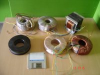
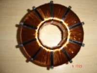
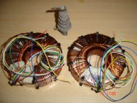
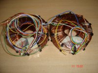
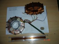
This is an old thread I made, but actually I want to add a photo of the transformers in question, although they aren't finished.
From left to right and from up to down: a heater toroidal transformer, with a secondary for the EL34 output stage, an isolated 6.3V for the driver tubes whose heater is at higher potential than ground, and other for grounded driver tubes; the +B transformer with the 3DG4 heater, the 12Hy 300 mA self designed and constructed, and 3 stages of the output toroidal UL transformers, but they are high frequency failed, so I´ll try another way of winding them.
Diskette is for size comparation only.
Attachments
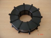
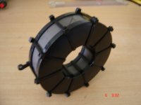
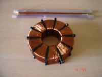
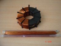
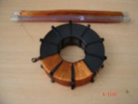
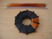
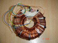
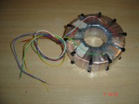
Transformers rework I.
I had reworked my output toroidal transformers this last 2 weeks, during vacations. It appears that my idea of section the core and winding there the primary has given good results. At least, the resonant frequency has moved from the original 8KH to almost 26KHz as I could measure in preliminary tests.
I had taken some photos of my job, and they are here.
Attachments
-
 Trafo 01.JPG138 KB · Views: 680
 -
 Trafo 02.JPG138.5 KB · Views: 676
 -
 Trafo 03.JPG150.4 KB · Views: 648
 -
 Trafo 0a.JPG131.3 KB · Views: 251
 -
 Trafo 09.JPG149.4 KB · Views: 226
 -
 Trafo 08.JPG151.8 KB · Views: 223
 -
 Trafo 07.JPG155.3 KB · Views: 210
 -
 Trafo 06.JPG135.4 KB · Views: 243
 -
 Trafo 05.JPG140.9 KB · Views: 635
 -
 Trafo 04.JPG138.7 KB · Views: 649
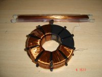
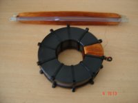
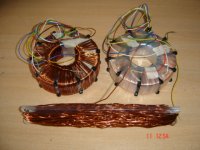
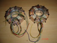
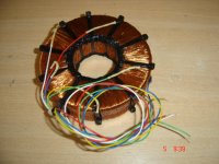
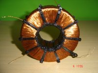
Transformers rework II.
I expressly want to say that the section the core is an own idea based on the old power RF choke in the photos, and that I didn't disassemble nor reverse engineered none commercial or standard transformer If the idea was already used is merely coincidence.
I expressly want to say that the section the core is an own idea based on the old power RF choke in the photos, and that I didn't disassemble nor reverse engineered none commercial or standard transformer If the idea was already used is merely coincidence.
Attachments
-
 Trafo 13.JPG156 KB · Views: 202
 -
 Trafo 12.JPG153.2 KB · Views: 204
 -
 Trafo 11.JPG150.2 KB · Views: 217
 -
 Trafo 10.JPG155 KB · Views: 213
 -
 Trafo 0f.JPG139.4 KB · Views: 223
 -
 Trafo 0e.JPG144.9 KB · Views: 222
 -
 Trafo 0d.JPG153.9 KB · Views: 215
 -
 Trafo 0c.JPG151.7 KB · Views: 225
 -
 Trafo 0b.JPG144.3 KB · Views: 273
 -
 Trafos 01.JPG144 KB · Views: 228
I expressly want to say that the section the core is an own idea based on the old power RF choke in the photos, and that I didn't disassemble nor reverse engineered none commercial or standard transformer If the idea was already used is merely coincidence.
Your idea is brilliant, regardless if someone did before.
")
BTW. Very nice transformers, a lot of work.
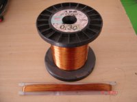
Yes, about 3 days working about 8-9 hours a day: 1 day per primary winding (3000 turns plus screen and +B taps without cutting the wire, and counting turn by turn mentally, and help only by the "digital counter" in the photo of the pen an the paper sheet), and 1 plus day to wind both secondaries, 110 turns of 1.2mm diameter copper wire. Finally, a tenths of minutes to solder output cables, put the isolating tape between primary and secondary, etc. But I did it by pleasure only. Work it good or bad, the try were interesting.
Thank you Popilin by the suggestions given in the telephone dialog.
Thank you Popilin by the suggestions given in the telephone dialog.
Yes, about 3 days working about 8-9 hours a day: 1 day per primary winding (3000 turns plus screen and +B taps without cutting the wire, and counting turn by turn mentally, and help only by the "digital counter" in the photo of the pen an the paper sheet), and 1 plus day to wind both secondaries, 110 turns of 1.2mm diameter copper wire. Finally, a tenths of minutes to solder output cables, put the isolating tape between primary and secondary, etc. But I did it by pleasure only. Work it good or bad, the try were interesting.
Thank you Popilin by the suggestions given in the telephone dialog.
Nothing to thank, for that are friends, right?
Thank you.In fer day's when the thermometer goes down, I'll try them.Nice work.
Shoog
I wish it's simple as that...
Toroids are prone to "saturation" or working on improper part of magnetization curve.
Secondly, gap, together with proper cross-section and number of turns is commonly used in SE amps to allow the core to operate at linear part of B-H curve, of course for steel.
Thirdly gap is linearizing dependence of permeability on DC bas.
So, regardless of the amount you want to spend, I would advise to get custom core with permeability around 4000-8000, AND, most importantly very linear curve, boxed, period
FT-3L by Hitachi, for instance. Anyway look for transverse annealed ones. Either amorph or noncrystalline.
Having done that - very cost prohibitive! Nice results...
WHY THEN?
Relatively low permeability makes it as insensitive to DC bias as C-core is, but without the gap present.
Linearity of B-H from zero bias up makes it free from even harmonics in magnetization current and, subsequently at the output... which is not the case with ANY electrical steel.
In regard to winding you need to keep coupling between primaries and secondary(-ies) equal. And all the windings should be evenly distributed on the core.
In case of amorph/noncrystalline cores adding the gap OR use of impregnated (not boxed) cores kills material peculiarity
P.S. attached are real B-H curves of a material with Mue around 15000 Bmax approx 0.4T
P.P.S. Do not be afraid to gap toroidal core, if it's made of steel - no difference to the C-core then - too much ado about nothing.
I agree with most of what you said but magnetisation current introduces ODD
harmonics, only remanenz or dc premagnetisation can produce even harmonics (additional)
Last edited:
- Home
- Amplifiers
- Tubes / Valves
- Homebrew Toroidal Output Transformer