Probably a long shot, but does anyone out there have a reference for a digital logic pseudo random noise generator?
I have an article somewhere, which I read several years ago, but I can’t find it. A bunch of TTL (XTAL osc / gates / shift registers) were used in a white/pink noise generator prior to the filter. The logic replaced the typically used amplified zener diode or reverse biased b-e junction.
Cheers,
Glen
G.Kleinschmidt said:Probably a long shot, but does anyone out there have a reference for a digital logic pseudo random noise generator?
It all depends on the quality you are looking for. Digital pink noise generator are esentially generating a random sequence, starting from a seed. Certain theorems regarding prime polynomials are guaranteeing the sequence has the maximum length allowed by the hardware, and that's it. You re-use the seed, you get the same sequence. This may or may not make you happy...
Otherwise, a good digital random generator needs either a very long sequence (read: lots of bits/registers in hardware) or an entropy collector to generate a quasi-random seed. It is pretty easy to do an entropy collector in software (by collecting things like local time, combined with the number of bytes in the current local disk partition, the date/time of the last logon, etc...), not so easy in hardware. The best pure hardware digital random generators are still using an analog noise source as an entropy collector, that is the same old surface zener breakdown. All cryptochips from Atmel, ST, etc... are using this technology, unfortunately I am not aware of any independent (without requiring software) solution. You may want to try one of this crypto chips, but it's indeed a long shot.
One cheap solution (but needing some software) is to use a PIC and compile a chunck of code implementing a good random generator. My preference would go towards a Diffie-Hellman implementation (the RSA basis), but you may chose whatever pleases you from www.sourceforge.com The advantage of such an implementation is that you will not be restricted to the hardware constraints and the solution is pure digital.
G.Kleinschmidt said:
I have an article somewhere, which I read several years ago, but I can’t find it.
A bunch of TTL (XTAL osc / gates / shift registers) were used in a white/pink noise generator prior to the filter.
The logic replaced the typically used amplified zener diode or reverse biased b-e junction.
Yes, GKlein.
I have also read such a project.
In Elektuur electronics magazine.
Using digital chips ( like TTL / CMOS )
we can produced a very 'controlled noise' and very consistent.
Be it white or pink or whatever.
There are some logic gate IC-s that can be coupled for deliver a random noise signal output.
Like some counters logics.
This project, using digital logic chips, which I refer to
was to make audio test output noise.
I have seen both WHITE and PINK noise generated this way.
Lineup
syn08 said:It all depends on the quality you are looking for. Digital pink noise generator are esentially generating a random sequence, starting from a seed. Certain theorems regarding prime polynomials are guaranteeing the sequence has the maximum length allowed by the hardware, and that's it. You re-use the seed, you get the same sequence. This may or may not make you happy...
Yes, from memory the published circuit used a bunch of 8 bit shift registers stringed togeather to give a relatively long word. I can’t remember how the “seed” was generated and preloaded though. However I do recall that there was something special about the seed that made the generator a bit "less" pseudorandom.
I asked because I’m considering doing this in a CPLD. Way back in my apprentice days I designed and built a character mapped video (VGA) 16 colour graphics generator, written into a Altera EPM7064 CPLD. Screen RAM was external as was the ROM (serial EEPROM - transferred into a fast operating parallel RAM on power-up) containing an extended ASCII character set with graphic characters. A PIC16F874 was the CPU.
I blatantly ripped off (pixel for pixel) the complete character set (text font, aliens, missiles) for the original Space Invaders game and programmed my own version of the game into the PIC.
It worked just like the arcade version, until I ran out of RAM on the PIC to store operating variables such as the status (exploded or not) of the missile barricades.
The project ended then and I went onto other things.
I’m planning on resurrecting the project to make a Rolls-Royce version of the 20 band discrete logic audio spectrum analyser just described, but with 30 bands instead (1/3 octave), a DSP doing “brick wall” frequency filtering and logarithmic conversion.
The video display will be entirely character based with on screen text to designate each bands Fc and the vertical graticule scale.
After that I’ve got a homebrew 1GS/s / 500MHz front end digital sampling oscilloscope adaptor to build (uses ten affordable 100MS/s video ADC’s interlaced by being clocked 36 degrees out of phase from a FPGA based 10 channel / 100MHz programmable master clock generator). Much cheaper than buying my own HP Infinium or Lecroy!
I’ve been equipping myself and building up my electronics workshop / garaging for a number of years now. I’m finally getting to the stage where I can start building stuff good and proper (as opposed to basic hobby stuff).
lineup said:
Yes, GKlein.
I have also read such a project.
In Elektuur electronics magazine.
Using digital chips ( like TTL / CMOS )
we can produced a very 'controlled noise' and very consistent.
Be it white or pink or whatever.
There are some logic gate IC-s that can be coupled for deliver a random noise signal output.
Like some counters logics.
This project, using digital logic chips, which I refer to
was to make audio test output noise.
I have seen both WHITE and PINK noise generated this way.
Lineup
The article I know I've got somewhere was from Electronics World (in the era of 74XX TTL logic). It was reprinted in another magazine (ETI, EA, AEM or something)

Cheers,
Glen
jackinnj said:How are you "detecting" the energy in each band? Peak, quasi-peak, RMS, average?
Quasi-peak. The only thing of interest is the relative amplitudes between frequency bands, so it really doesn't matter if it's peak, quasi-peak, RMS or average, so long as each band is detected the same way.
Cheers,
Glen
G.Kleinschmidt said:
After that I’ve got a homebrew 1GS/s / 500MHz front end digital sampling oscilloscope adaptor to build (uses ten affordable 100MS/s video ADC’s interlaced by being clocked 36 degrees out of phase from a FPGA based 10 channel / 100MHz programmable master clock generator). Much cheaper than buying my own HP Infinium or Lecroy!
Yep, I'm sure this was an interesting project. Me, the only things that I am interested to build are a) things never done before (performance or solution wise) and b) things that are equivalent (performance, solution) to obvious commercial snake oil ripoffs (as is most of the high end audio today).
Regarding a 1GS/sec scope, I can get a second hand Tektronix TDS210 (60MHZ, though) for $300 - brand new is $1700. I certainly doubt I could build today such a device for $300...
Attachments
G.Kleinschmidt said:Quasi-peak.
------------
... long as each band is detected the same way.
The main feature issue, regarding vertical scale, would be the resulotion.
0.1 dB .. 1 dB ... or adjustable/selectable?
If step is e.g. 3 dB, then some different levels below this will show as equal.
Too high resulotion gives a limited total range.
Too low resulotion gives a level of accuracy that may not be acceptable.
lineup said:
The main feature issue, regarding vertical scale, would be the resulotion.
0.1 dB .. 1 dB ... or adjustable/selectable?
If step is e.g. 3 dB, then some different levels below this will show as equal.
Too high resulotion gives a limited total range.
Too low resulotion gives a level of accuracy that may not be acceptable.
Lineup, only the graticule divisions are at 3db intervals, the level bars are limited by the vertical resolution of 512 lines, each 32uS long (320 of which are used for the display). This works out to 0.09375dB.
I hope to get a video of the completed prototype unit operating with a music signal up on YouTube maybe the weekend after next.
Cheers,
Glen
syn08 said:Regarding a 1GS/sec scope, I can get a second hand Tektronix TDS210 (60MHZ, though) for $300 - brand new is $1700. I certainly doubt I could build today such a device for $300...
The goal of the homebrew unit is to develop a DSO with a flexible PC interface. You don't get that with a cheapie lunchbox DSO. And those budget DSO's are noisy as fk on the low volts/cm ranges.
jackinnj said:
Nice!
Cheers,
Glen
jackinnj said:
That is a really nice part. With 10 of them I can whack up a really simple no fuss analogue board for a 60 band (20Hz-20kHz) audio spectrum analyzer with excellent resolution, without having to buy an expensive DSP eval. board.
If they are not too expensive I'll order myself a bunch for the next analyzer.
Thanks!
G.Kleinschmidt said:
If they are not too expensive I'll order myself a bunch for the next analyzer.
Thanks!
If anyone can find out where to get some, I'd like to get my hands on some of those chips too !
Argo.
argofanatic said:
If anyone can find out where to get some, I'd like to get my hands on some of those chips too !
Argo.
Being no listed distributor here in Oz, I did what the datasheet says and emailed MSI yesterday morning for pricing and MOQ.
No reply yet. Slack
Cheers,
Glen
Glen
You have any webpage for this project
I mean at your website:
http://users.picknowl.com.au/~glenk/
Where u post some short progress info / pictures
You have any webpage for this project
I mean at your website:
http://users.picknowl.com.au/~glenk/
Where u post some short progress info / pictures
lineup said:Glen
You have any webpage for this project
I mean at your website:
http://users.picknowl.com.au/~glenk/
Where u post some short progress info / pictures
I've been posting updates here Lineup. When I have finished building it a webpage for it with all details will go up on my site. Currently laying out the PCB's (It seems I will be etching my own boards, so it's all SMD - don't want to drill holes for a few dozen DIPs).
Cheers,
Glen
G.Kleinschmidt said:
Being no listed distributor here in Oz, I did what the datasheet says and emailed MSI yesterday morning for pricing and MOQ.
No reply yet. Slack
Cheers,
Glen
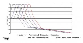
The MSSCSSA is a bank of switched capacitor filters set up in bandpass configuration. You can do much the same thing "in solder" -- but it will be expensive and time consuming to lay out.
I like the skirts on crystal filters better than RC, but the last time I worked with a DIY crystal filter on my own was with a SSB exciter over 40 years ago.
jackinnj said:
The MSSCSSA is a bank of switched capacitor filters set up in bandpass configuration. You can do much the same thing "in solder" -- but it will be expensive and time consuming to lay out.
I like the skirts on crystal filters better than RC, but the last time I worked with a DIY crystal filter on my own was with a SSB exciter over 40 years ago.
Not too many crystals cut for audio frequencies though!
. I guess one could up convert to a MHz or so and xtal filter then, but the last time I had a single xtal cut it was something like $17.Have you had a play with that MSI chip? The datasheet is pretty sparse. There is no mention of Fclock feed through - which would dictate how much (if any) post bandpass low-pass filtering (and thus, to a large degree, the complexity of a 60 band filter/detector board) is required for a given S/N ratio.
Cheers,
Glen
- Status
- This old topic is closed. If you want to reopen this topic, contact a moderator using the "Report Post" button.
- Home
- Amplifiers
- Solid State
- Homebrew Digital Sampling Audio spectrum analyser.