I've said it before and I'll say it again.
Working on something when one is tired is just a stupid thing to do.
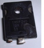
Somehow I managed to swap a irfp9240 for a irfp240 and vice versa... No wonder I was consuming too much current and everything was screwey!!!!
Once again my Variac probably saved my A$$, and a few parts but I won't know until I get them out and test them.
As bugs bunny would say... "WHAT A MA-ROON"

Working on something when one is tired is just a stupid thing to do.
Somehow I managed to swap a irfp9240 for a irfp240 and vice versa... No wonder I was consuming too much current and everything was screwey!!!!
Once again my Variac probably saved my A$$, and a few parts but I won't know until I get them out and test them.
As bugs bunny would say... "WHAT A MA-ROON"
Banned
Joined 2002
well yuo should get some sleep then.. never power stuff up at night i learned that the hard way see..
This is what happens when working on my blue amps at 4am so excited to get them going and well one blew up: O ) easy fix just replaced both fets and re bias-d till this day they still work. and also till this day i never power things up past 12 at night. L O )
This is what happens when working on my blue amps at 4am so excited to get them going and well one blew up: O ) easy fix just replaced both fets and re bias-d till this day they still work. and also till this day i never power things up past 12 at night. L O )
Attachments
I have to say one thing to anyone considering electronics as a hobby...
If you don't own a variac and your next purchase is NOT a variac then you should be slapped!
My variac has already saved me it's purchase price in parts that would have blown up if I hadn't had a variac.
Of course that doesn't say a whole lot for me now does it...
Jason... I'll get you some pictures when I can.
Frazzled
Banned
Joined 2002
Next Problem
OK...
Installed the output devices in the other board and tried to do initial testing, got 46mv offset voltage but couldn't get the bias to come up. Hooking up my meter across Q22 or any of the other output source resistors gave the same 0 reading and P1 seemed to have no effect on bias.
So... I fed a 1khz 100mv sinewave into the amp and looked at the output with no load...
The bottom wave is the input and the top wave is the output (about 25v p-p)
I connected a speaker to the output and this is what I got...
Again top waveform is output, hmmmmmmm...
I hooked up a CD player to the input and the sound I got out was very enemic and distorted but I could hear the sound of a square wave in the audio so I disconnected the cd player and went hunting...
Found this at the junction of R38 and R22.
I disconnected the speaker and this square wave instantly vanished.
The following is the output (top waveform) and the junction of R38 and R22 with 1khz @ 100mv sine wave at the input...
Well it looks like I have much more work ahead of me...
OK...
Installed the output devices in the other board and tried to do initial testing, got 46mv offset voltage but couldn't get the bias to come up. Hooking up my meter across Q22 or any of the other output source resistors gave the same 0 reading and P1 seemed to have no effect on bias.
So... I fed a 1khz 100mv sinewave into the amp and looked at the output with no load...
An externally hosted image should be here but it was not working when we last tested it.
The bottom wave is the input and the top wave is the output (about 25v p-p)
I connected a speaker to the output and this is what I got...
An externally hosted image should be here but it was not working when we last tested it.
Again top waveform is output, hmmmmmmm...
I hooked up a CD player to the input and the sound I got out was very enemic and distorted but I could hear the sound of a square wave in the audio so I disconnected the cd player and went hunting...
An externally hosted image should be here but it was not working when we last tested it.
Found this at the junction of R38 and R22.
I disconnected the speaker and this square wave instantly vanished.
The following is the output (top waveform) and the junction of R38 and R22 with 1khz @ 100mv sine wave at the input...
An externally hosted image should be here but it was not working when we last tested it.
Well it looks like I have much more work ahead of me...
Referencing the pcb silkscreen designators;
Is the Q3, Q4 (2SA1306) installed correctly ? BCE Orientation is
opposite of Q23 - Q25. I was looking at those pics you posted,
hard to tell, but double check.
http://home.pacbell.net/lordpk/amplifier/Av800-2.jpg
Is the Q3, Q4 (2SA1306) installed correctly ? BCE Orientation is
opposite of Q23 - Q25. I was looking at those pics you posted,
hard to tell, but double check.
http://home.pacbell.net/lordpk/amplifier/Av800-2.jpg

Something isn't right. I think you should start to measure all DC voltages and check those against the theoretical ones. Then you should check all transistors if you have placed them right and turned them right. If you swap collector and emiiter the transistor will work but it can only handle 7-15 volts and the gain is 3-7 only. This can produce weird results.
I remember on my symmetrical 400 that one of the tranistors (the bias transistor) the collector and emmitter were reversed... it was to be soldered w/ flying leads anyway, but on the silkcreen (which was technically correct although confusing) ... it said the correct thing, but the collector and emmitter were different from the pinout on the actual transistor. That was the only trouble i had getting mine running. So, check the pinouts if you are doing anything w/ flying leads. Later
-Matthew K. Olson
-Matthew K. Olson
Testing
Did some testing this morning and here is what I found...
Remember this is the board (#2) that sat untested until I got the major bugs worked out on the other board (#1), so board #2 hasn't had to suffer any of the atrocities that #1 went through during initial testing and #2 had all of the changes made to it prior to power up.
Again I brought the amp up to full +/-90Vdc rails.
Grounded the inverting input and connected my function generator set at 100mv @ 1Khz sine to the non-inverting input, and no load.
Checked the waveform from the input following the signal path but it wasn't long before I ran into trouble...
Bottom waveform is always input.
This is the signal at the base of Q6 (BC5468)...
Closer...
Now at the collector of Q6...
And the emitter...
I guess I should start isolating the different parts of the input and VA stages to see if I can track down the source of this problem.
Did some testing this morning and here is what I found...
Remember this is the board (#2) that sat untested until I got the major bugs worked out on the other board (#1), so board #2 hasn't had to suffer any of the atrocities that #1 went through during initial testing and #2 had all of the changes made to it prior to power up.
Again I brought the amp up to full +/-90Vdc rails.
Grounded the inverting input and connected my function generator set at 100mv @ 1Khz sine to the non-inverting input, and no load.
Checked the waveform from the input following the signal path but it wasn't long before I ran into trouble...
Bottom waveform is always input.
This is the signal at the base of Q6 (BC5468)...
An externally hosted image should be here but it was not working when we last tested it.
Closer...
An externally hosted image should be here but it was not working when we last tested it.
Now at the collector of Q6...
An externally hosted image should be here but it was not working when we last tested it.
And the emitter...
An externally hosted image should be here but it was not working when we last tested it.
I guess I should start isolating the different parts of the input and VA stages to see if I can track down the source of this problem.
Banned
Joined 2002
I should email this page to anthony E then he can see and maybe help.. i believe he is back now. Keep you head up dont give up.. and dont work to long on it all day take time away from it or youll make bigger or more stupid mistakes .. * lesson learned the hard way *
i am pretty glad my dad was there to help me when i first worked an powered up my n-channel. it is a great little amp.. Good job on anthony's part.. just lack of instruction's that is all..
i am pretty glad my dad was there to help me when i first worked an powered up my n-channel. it is a great little amp.. Good job on anthony's part.. just lack of instruction's that is all..
Take closeup pics of your new board so we can see details
of your assembly.
Did you check the bottom side of the pcb for solder bridges?
My rule of thumb when performing amplifier repair is to always
check the semiconductors, double and triple check,
possibly even replacing them with fresh ones for sanity reasons.
Holton claims the AV800 design works and has been in the field
for years, it's just a matter of time of finding the gremling that
gives you grief.
Keep in mind that if you found a problem and corrected it, it
also raises the question if something else got damaged. I would
recheck all your components out of circuit
thylantyr said:Take closeup pics of your new board so we can see details
of your assembly.
Did you check the bottom side of the pcb for solder bridges?
YES I DID
My rule of thumb when performing amplifier repair is to always
check the semiconductors, double and triple check,
possibly even replacing them with fresh ones for sanity reasons.
I HAVE AND IT IS DRIVING ME NUTS
Holton claims the AV800 design works and has been in the field
for years, it's just a matter of time of finding the gremling that
gives you grief.
YES BUT HAVE YOU EVER TALKED TO SOMEONE WHO HAD A WORKING AV800
Keep in mind that if you found a problem and corrected it, it
also raises the question if something else got damaged. I would
recheck all your components out of circuit
AS I STATED BEFORE THIS IS THE BOARD THAT HAD ALL THE CHANGES MADE TO IT PRIOR TO POWERING UP SO NOTHING COULD HAVE BEEN DAMAGED DUE TO TESTING CAUSE NONE WAS DONE, THE OTHER BOARD TOOK ALL THE ABUSE.
I have taken a day away from the project to do some reading and to clear my head, sometimes staring at the same problem too long causes you brain to sieze up. I think I will have another go at it later today.
Frazzled


Banned
Joined 2002
If there are working AV800s out there, I haven't heard about them. But that doesn't mean there is anything wrong with the PCBs. There are so many chances for a bad connection or imperfect part value in this amp. But since you noted that the input/VAS stage currents are correct then the problem is probably in the Vbe multiplier or the buffer stage; you still can't get any bias current in the output stage, right?
2. Hammer
Maybe we should send Carlos (aka DestroyerX) around with his double barrel shotgun. Seems to fix the amps he doesn't like.
On a serious note, I find you end up learning a lot more from an amp that doesn't work than one that went together faultlessly. I know this doesn't relieve the frustration. Shame Anthony isn't there to help.
Check the pinout on Q8, w/ flying leads. On my symmetrical 400 i had trouble w/ it..
look at page 4 "preflight test" on the symmetrical 400 pdf, if you notice, anthony does mention that the pcb is different than the pinout on the device
the av800 may have a similar issue
just an idea
-Matthew K. Olson
look at page 4 "preflight test" on the symmetrical 400 pdf, if you notice, anthony does mention that the pcb is different than the pinout on the device
the av800 may have a similar issue
just an idea
-Matthew K. Olson
Mattyo5 said:Check the pinout on Q8, w/ flying leads. On my symmetrical 400 i had trouble w/ it..
look at page 4 "preflight test" on the symmetrical 400 pdf, if you notice, anthony does mention that the pcb is different than the pinout on the device
the av800 may have a similar issue
just an idea
-Matthew K. Olson
DONE
On another note, as I am finding errors I am updating the construction guide to reflect the correct information.
I just wish I could correct the PCB as easily.
If and when I ever DO get this amplifier working, I will also have a 100% complete and accurate construction guide, INCLUDING SCHEMATIC, to go along with.
I will offer it to Anthony Holton to host on his site and will make it available to anyone who is currently or contemplating building the AV800.
Frazzled.
- Status
- This old topic is closed. If you want to reopen this topic, contact a moderator using the "Report Post" button.
- Home
- Amplifiers
- Solid State
- Holton AV800 Schematic