is there a simulation program using given parameters of loudspeakers, without measuring tools or if I don't have measuring tools?
Yes, just do a search for loudspeaker box design tools. Many are free.
WinIsd is popular.
However, you really need to measure both the driver and the completed loudspeaker to get things right. Simulations only go so far.
You can do this cheaply with an electric condenser mic element and make your own mic or buy a good mic from Parts Express, etc.
You need a sound card that will accept a mic input, but many use a USB interface box that supports phantom power for the electric mic.
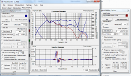
Hi, please, I'd like to ask you about my measurement attempt in Holm. I'am trying to develop crossover for 2way system with Visaton WS20 and G25 FFL tweeter with Waveguide WG148. Please see the attached photo. I am not sure about the oscillations before the main peak in tweeter measurement. Woofer has nice smooth impulse. But where should be the zero time in this measurement ? Thanks a lot.
Note: (I am using ASIO USB sound card ARES SC4, 48kHz, lowcost Megaton M-1 calibrated mic + 3dB preamp and LineIN).
Note: (I am using ASIO USB sound card ARES SC4, 48kHz, lowcost Megaton M-1 calibrated mic + 3dB preamp and LineIN).
Attachments
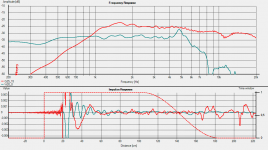
pre-ringing indicatrs a problem with the measurement. strange tha you don't see it on the woofer measurement. I'd try again after a full system shutdown and startup.
If you are measuring on your final baffle, I would set the time zero on the tweeter measurement (make sure you tell it to do it twice, the first time it is slightly off. Then go to the second tab and lock time zero before measuring your woofer. This ensures that your phase data is correct for your crossover modelling.
Tony.
Thank you for the reply. Anyway, if you see another attached pic (test measurement during mic calibration); here is quite strange behaviour when calibration is ON or OFF. When it's OFF, pre-ringing amplitude is much smaller then mic cal. is ON. How is it possible ?
Attachments
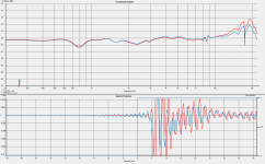
I suspect that there is some feedback happening. Check your settings to make sure that the sound card is not "monitoring" what is coming in on the line in. Some sound cards have a setting that sends the incoming line in back out the line out. This results in feedback and screwed up measurements.
Also make sure nothing is running that is changing settings on the sound card. particularly problematic are things like itunes.
My guess is that the problem was present when you tried to calibrate, and the adjustments that the calibration file is trying to do are making things worse.
What did your loopback measurement look like for your calibration? It doesn't hurt to do a loopback measurement every time you set up to do measurements just to make sure everything is working properly. If you can get a clean loopback then there shouldn't be any issues related to sound card config.
If the worst comes to the worst, find the holm impulse directory under your user home directory and delete all of the files there (usually a couple of xmls and a zip with the measurements in it (make a backup first). Sometimes something gets corrupted and this is the only way to get it working properly again. Note that all settings will return to defaults if you do this.
Tony.
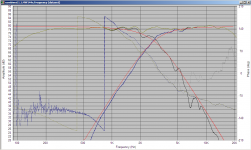
Thanks, it's possible, that there were some other apk's running during measurement (maybe youtube in IE + SoundForge). I'll try it once again on pure Win7. Anyway. I've stored only this screenshot frm loopback test (I haven't got original Holm data now :/ )
Attachments
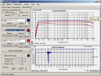
Hmmm I definitely thing that something is not right. One of your apps may be turning on EQ on your sound card's dsp. there is a lot of rolloff there from about 5Khz on. I would not expect that at all on a loopback measurement if everything is working properly. maybe 0.2 or 0.3db by 20Khz.
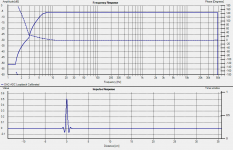
Attached is a loopback measurement of my usb focusrite 2i2 (after calibration) set at 96Khz.
Note that the attached result is VERY flat, and not all cards can be expected to be this good, however I would expect a better result than the one you have shown.
Double check all the settings for your sound card especially any for effects or eq (making sure they are off).
Tony.
Attachments
For those of us that don't have anechoic chambers, huge baffle boards and mega thousand dollar calibrated measurement mics, what would be be best way to measure the FR of a particular driver? Nearfield?
Of course, an SPL measurement wouldn't be accurate except to ones own measurement parameters. Meaning always use the same gain on the amp and the same distance from the speaker.
Of course, an SPL measurement wouldn't be accurate except to ones own measurement parameters. Meaning always use the same gain on the amp and the same distance from the speaker.
Hi Thump Lump, I guess the answer to that is "It depends" ")
If you want something that approximates manufacturers spec type measurements taken on an IEC baffle, then I'm not sure. Nearfield is only accurate up to a certain frequency (from memory dependent on the driver diameter), and that frequency is not very high.
If you want measurements that you can use for crossover design then the best measurements are those taken in the actual enclosure as they include the baffle diffraction effects.
I generally do my measurements at around 1M (mainly because it is difficult to get more than that distance to any other reflecting surfaces.
If you have a quiet outside area and can elevate the speaker say to 2M away from any nearby surfaces you should be able to get good measurements down to at least 200Hz and probably lower. You can then use (baffle diffraction corrected) nearfield measurements for the lower frequencies spliced into the 1M measurements.
Ground plane measurements (I haven't tried these as I don't have a suitable area to do them) may be another option.
Tony.
If you want measurements that you can use for crossover design then the best measurements are those taken in the actual enclosure as they include the baffle diffraction effects.
I generally do my measurements at around 1M (mainly because it is difficult to get more than that distance to any other reflecting surfaces.
If you have a quiet outside area and can elevate the speaker say to 2M away from any nearby surfaces you should be able to get good measurements down to at least 200Hz and probably lower. You can then use (baffle diffraction corrected) nearfield measurements for the lower frequencies spliced into the 1M measurements.
Thanks. Sounds like that will be what I will have to do. Outside and up in the air. I do have a nice Quickset Husky tripod that should support a good amount of weight. At least enough for 2 way bookshelf speaker cabinets. Should I set it up as close to 1 watt @ 1 meter as I can get to try and get a comparable SPL reading?
Now that it's getting warmer, this is doable.
When I did my latest measurements I played a 100Hz tone and measured the AC voltage at the speaker terminals (adjusted to 2.83V) Just make sure you remove the multimeter before doing the measurement as it can interfere.
Note that without a known accurate SPL meter though that you won't be able to get absolute SPL measurements as you don't know what the sensitivity of your mic, preamp, soundcard interface is.
Tony.
Note that without a known accurate SPL meter though that you won't be able to get absolute SPL measurements as you don't know what the sensitivity of your mic, preamp, soundcard interface is.
Tony.
I have one of the newer Radio Shack SPL meters with the digital read out (as opposed to the older analog readout) and they are suppose to be fairly accurate.
I also found this Wiki page that was informative as well. When you said "ground plane" I assume that is the same as "half space" as mentioned on the Wiki page?
I also found this Wiki page that was informative as well. When you said "ground plane" I assume that is the same as "half space" as mentioned on the Wiki page?
Would probably help if I posted the page link. DUH. Loudspeaker measurement - Wikipedia, the free encyclopedia
No, they're not the same. The half space measurement referenced in the link would show you the response of the speaker in the enclosure but not including baffle step / diffraction effects if you mounted the speaker into the ground so the front baffle was flush with the ground. If you just pointed it up, you'd get a reflection off the ground that would be very close in time to the direct sound from the speaker.
Groundplane means placing the mic on the ground. Then you point the speaker towards the mic. So if you have a sub and you only care about low frequencies, just set it on the ground pointed at the mic. If you want to measure a full range speaker, you'll need to tip the speaker so that the axis of the speaker you're interested in is pointed at the mic. There's a paper by Don Keele describing this technique that I remember being pretty good. You will see the effects of baffle step with this technique. Find a big empty parking lot to do it in.
Groundplane means placing the mic on the ground. Then you point the speaker towards the mic. So if you have a sub and you only care about low frequencies, just set it on the ground pointed at the mic. If you want to measure a full range speaker, you'll need to tip the speaker so that the axis of the speaker you're interested in is pointed at the mic. There's a paper by Don Keele describing this technique that I remember being pretty good. You will see the effects of baffle step with this technique. Find a big empty parking lot to do it in.
I am very rusty re the phase side of the measurement things and was hoping somebody may be able to confirm my thoughts.
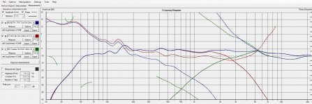
The image below shows the XO setup I've just about settled on, which is a Mid/Woofer 4th Ord XO at 2.8khz & the Tweeter 2nd Ord at 3.0khz. The actual crossover point is at about 2.57khz.
It was my understanding that the phase lines should XO at 2.57khz, where mine are crossing over at about 5.35Khz. If I am correct, it means I need to add a delay that will cross the phase lines at 2.57khz.
Can anyone confirm that my understanding is correct.
Attachments
Hi DQ828 I think that your phase looks a bit screwy. Mostly on the Mid woofer. The phase for the tweeter looks more normal...
Did you Zero lock the measurements after measuring the tweeter? For the measurements to be useful in crossover design they should include the delay (unless you are using minimum phase and putting in the driver offsets).
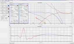
How you set the time zero can dramatically affect the way the phase is displayed. have a look at the attached. This is the same measurement of a 10" woofer taken outside. With two different time zero settings. This is why I think it is important to zero lock time zero after doing the tweeter measurement. That way the phase of the second driver is locked to the first so any variations are real variations. If you adjust time zero for each driver independently then there is no telling what is realistic with respect to the phase matching of the two drivers.
Note also that in the crossover region, you don't so much want the phase lines crossing each other as to be in alignment with each other, the further either side of the crossover frequency that they match up the better! Both should be sloping in the same direction more or less and be as close to each other as possible. Second attachment is an example from my MTM crossover which has a crossover frequency of around 2.8Kz.
Tony.
Did you Zero lock the measurements after measuring the tweeter? For the measurements to be useful in crossover design they should include the delay (unless you are using minimum phase and putting in the driver offsets).
How you set the time zero can dramatically affect the way the phase is displayed. have a look at the attached. This is the same measurement of a 10" woofer taken outside. With two different time zero settings. This is why I think it is important to zero lock time zero after doing the tweeter measurement. That way the phase of the second driver is locked to the first so any variations are real variations. If you adjust time zero for each driver independently then there is no telling what is realistic with respect to the phase matching of the two drivers.
Note also that in the crossover region, you don't so much want the phase lines crossing each other as to be in alignment with each other, the further either side of the crossover frequency that they match up the better! Both should be sloping in the same direction more or less and be as close to each other as possible. Second attachment is an example from my MTM crossover which has a crossover frequency of around 2.8Kz.
Tony.
Attachments
Last edited:
I tried measuring the tweeter first and then locking the time (Time Zero Locked) and I get what you see in the attached.
If I'm reading the data correctly the drivers are 8cm out of alignment!!!
More like 8mm in the real world.
I am using the Active Analogue filter boards from the Active Filter Board GB that was run some time ago. I have included an All Pass to delay the signal the 8mm.
Any thoughts?
If I'm reading the data correctly the drivers are 8cm out of alignment!!!
More like 8mm in the real world.
I am using the Active Analogue filter boards from the Active Filter Board GB that was run some time ago. I have included an All Pass to delay the signal the 8mm.
Any thoughts?
Attachments
What distance was the measurement taken and what axis (on axis with the tweeter?) If you work out the geometry of the triangle between the mic, tweeter and mid, would there potentially be 8cm difference between the distance between the tweeter and the mic, and the mid woofer and the mic?
Also I note that the gating on the tweeter measurement is different to the gating on the mid measurement, you should probably bring the two into alignment.
Are the measurements shown with the active filter in use? If they are can you do the measurements with the raw drivers?
Tony.
Also I note that the gating on the tweeter measurement is different to the gating on the mid measurement, you should probably bring the two into alignment.
Are the measurements shown with the active filter in use? If they are can you do the measurements with the raw drivers?
Tony.
- Home
- Design & Build
- Software Tools
- HOLMImpulse: Measurements in practice