Hello,
If the first cap after the rectifier is to big it surely can overheat the rectifier because charging pulses will get bigger. It is the big pulses that cause the heat. If you make a le monstre with a proper choke input the current through the choke will be practically the same as the current taking by the circuit itself.
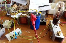
Take a good look at my choke input heater supply with Rod Coleman circuit.
You see the 4 small diodes soldered directly at the transformer. After diodes ll2733 choke input than big cap that i always use for testing then regulator circuit then vt25a tube that takes 1,25A
Because of the right choke current is 1,25A all the time so diode can be 2A model even with big cap.. temperature of diode after 4 hours 35 degrees Celsius.
Once i calculated the price for each mH for a few chokes made by Lundahl.
The ll2771 is the best. Must be used with its two coils in series to get 700mH 2A it works perfect in my friends 20 watt Hiraga ( i build it 30 years ago) with bias current 1A in each channel . For the 30 watt Hiraga you must use another one with less mH and more A
We tried the hiraga with 1,2A each side but that is to much for the ll2771.
For le monstre ll2771 is the best.
Greetings,Eduard
If the first cap after the rectifier is to big it surely can overheat the rectifier because charging pulses will get bigger. It is the big pulses that cause the heat. If you make a le monstre with a proper choke input the current through the choke will be practically the same as the current taking by the circuit itself.
Take a good look at my choke input heater supply with Rod Coleman circuit.
You see the 4 small diodes soldered directly at the transformer. After diodes ll2733 choke input than big cap that i always use for testing then regulator circuit then vt25a tube that takes 1,25A
Because of the right choke current is 1,25A all the time so diode can be 2A model even with big cap.. temperature of diode after 4 hours 35 degrees Celsius.
Once i calculated the price for each mH for a few chokes made by Lundahl.
The ll2771 is the best. Must be used with its two coils in series to get 700mH 2A it works perfect in my friends 20 watt Hiraga ( i build it 30 years ago) with bias current 1A in each channel . For the 30 watt Hiraga you must use another one with less mH and more A
We tried the hiraga with 1,2A each side but that is to much for the ll2771.
For le monstre ll2771 is the best.
Greetings,Eduard
Attachments
Hello,
This is heater supply so it has just plus and gnd. The Lundahl does have two coils.
Lundahls tells us in their datasheet then you can use one coil on the LL2733 on the plus side and the other coil in the GND side.
I case of our power amps you need to put these 2 coils in parallel ( there is only one way to do it correct , see the pdf) and put that in the +rail and then another LL2771 with 2 coils parallel in the min rail.
My friend in Vietnam uses LL2733 400mH 1,7A in the single rail supply of his single ended Nelson Pass design the same way like i use it in my heater supply. And for the other channel he uses another LL2733
At that time the LL2771 was not available yet. I took the LL2733 fromm the Netherlands all the way to Vietnam.
The LL2771 gives more return on investment. If you order it in Estonia they will send it tax free. If you order plus 300 euro no shipping cost but you can ask my Brazilian friend about that. He decided to buy a choke for a tube amp to so now for 30 $ more he has free shipping and an extra choke.
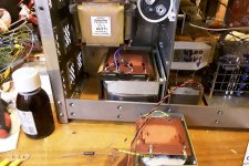
In one photo you see my DDDAC 1A continuous current and tiny diodes.
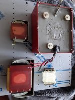
In other photo:
Big R core with LL2733 choke input for my DDDAC
New smaller but big enough and LL2771 choke input for DDDAC much better.
The R core is now used in my friends 20 watt Hiraga CLC supply also with ll2771
Greetings, Eduard
This is heater supply so it has just plus and gnd. The Lundahl does have two coils.
Lundahls tells us in their datasheet then you can use one coil on the LL2733 on the plus side and the other coil in the GND side.
I case of our power amps you need to put these 2 coils in parallel ( there is only one way to do it correct , see the pdf) and put that in the +rail and then another LL2771 with 2 coils parallel in the min rail.
My friend in Vietnam uses LL2733 400mH 1,7A in the single rail supply of his single ended Nelson Pass design the same way like i use it in my heater supply. And for the other channel he uses another LL2733
At that time the LL2771 was not available yet. I took the LL2733 fromm the Netherlands all the way to Vietnam.
The LL2771 gives more return on investment. If you order it in Estonia they will send it tax free. If you order plus 300 euro no shipping cost but you can ask my Brazilian friend about that. He decided to buy a choke for a tube amp to so now for 30 $ more he has free shipping and an extra choke.
In one photo you see my DDDAC 1A continuous current and tiny diodes.
In other photo:
Big R core with LL2733 choke input for my DDDAC
New smaller but big enough and LL2771 choke input for DDDAC much better.
The R core is now used in my friends 20 watt Hiraga CLC supply also with ll2771
Greetings, Eduard
Attachments
With the Hiraga design current running is bigger so the way to connect can be even more important. Connecting the caps with copper bars is nice. BUT you have to know where to connect the wires to these bars. It has been said before with copies from Hiraga article but people still do it wrong.
I cannot see why the location of the connection points would be critical.
We tried the hiraga with 1,2A each side but that is to much for the ll2771.
That`s far too much for the transistors as well, in my humble view.
Caps nowadays arent that expensive anymore and they have gotten much smaller.
...and qualitatively much worse.
Hello Helmut,
You can check if the choke really works like a choke or just like a thick wire with 0,5 ohm DCR.
0,5 ohm is difficult to measure with a normal DNM meter
Same for the choke because you have to know the mH at a current comparable to the one taken by your circuit.
Like i wrote some post ago when used for choke input a choke ( working as a choke at the current present) with 0,5 ohm dcr will give a totally different voltage drop then a 0,5 ohm resistor! The difference could be 7,8,9 volts. If there is little difference it looks like a choke but it does not work like a choke. When it will not saturate it can be a little better than the 0,5 ohm but it surely is not a choke input so it will not have the benefits.
Greetings, Eduard
Any transistor regardless of technique. I consider standing currents above 1 A as a flagrant abuse. I am personally not fond of bipolar transistors in the output stage.
I have no issues running transistor high (around 1/4 rated power), cooling is usually the issue, keep them below 60c and they will be fine. Any transistor I have ever had fail has been well over 20years old, and as these are consumer goods I think they have fulfilled their pupose by that stage in life.
For evidence I would present my KSA150 which is still doing find and running amazingly well for something built in 93 (small caps have been changed).
On that same note, I have reservoir capacitors which are in some cases 35years old running in hot old Counterpoint amps, which measure well above original rating despite running around 45c. The ones that fail tend to be the little ones which are cramped into hot spaces.
That being said, I had a 5 year old Audiolab DAC which had to have all 60+ caps replaced despite these never getting over 35c, just a bad batch from what I can gather.
On another note, to anyone thinking of building the Monstre's, don't let the complexity that this thread is falling into put you off. These little amps are super easy to build and modify once built. You can take these to any level you want, big caps, small caps, the results are great even with "underspecced" power supplies.
Just remember to star earth them (they are sensitive to hum) and you should be fine. Hopefully building a basic version will peak your interest and lead you to experiment, the results with just minor changes can be big!
Just remember to star earth them (they are sensitive to hum) and you should be fine. Hopefully building a basic version will peak your interest and lead you to experiment, the results with just minor changes can be big!
Dear Konst,
You got to the point! Reading the material that Mr Eduard posted a link on the thread #1896, I realized that is an important difference between Audio Signal Ground, which I think is the connection between last 4 caps (2 + and 2 -) that provides the return path for the audio signal.
But, here are you talking about safety earth, right? Would you please help me to understand how to create a star earth in this case? Should it be a central point in the chassi, coming from the Audio Signal Earth, where all ground wires (speakers, circuits, meters, etc) must be connected?
Tks!
Nilton
Intelligent answer (which I do not have)
Hey there, I am not yet ready to explain it as I simply do not yet know. The chassis I have is too small to try anything interesting in and I have a bigger one coming.
I have recently disassembled and old Krell KMA200 which was working but the only one of its type and which will be converted to a ksa100 with the parts.
Looking at the way Krell did things is very interesting, they lift the ground from safety earth using several resistors and caps, which obviouisly worked well for them. That is going to be my starting point going forward, at the moment I have everything bolted to a single screw attached to the chassis, and it introduces just the slightest earth loop. If you look around, there are various diode/R/C schemes that people are trying out to separate safety from signal ground. I am sure Ed will have a better idea of what I am talking about than I do
I posted the pictures below in May 2013 after I finished building my Aleph J clone. The first two show the middle connection from the AC inlet directly to the chassis (safety ground or earth) using a piece of green wire.
The third picture shows how the PSU board ground (audio ground) is connected to the chassis using a NTC thermistor.
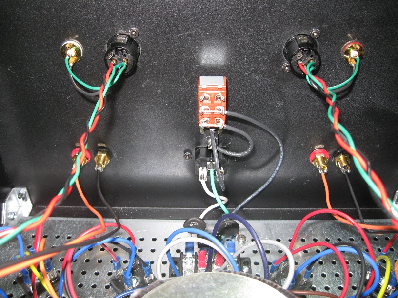
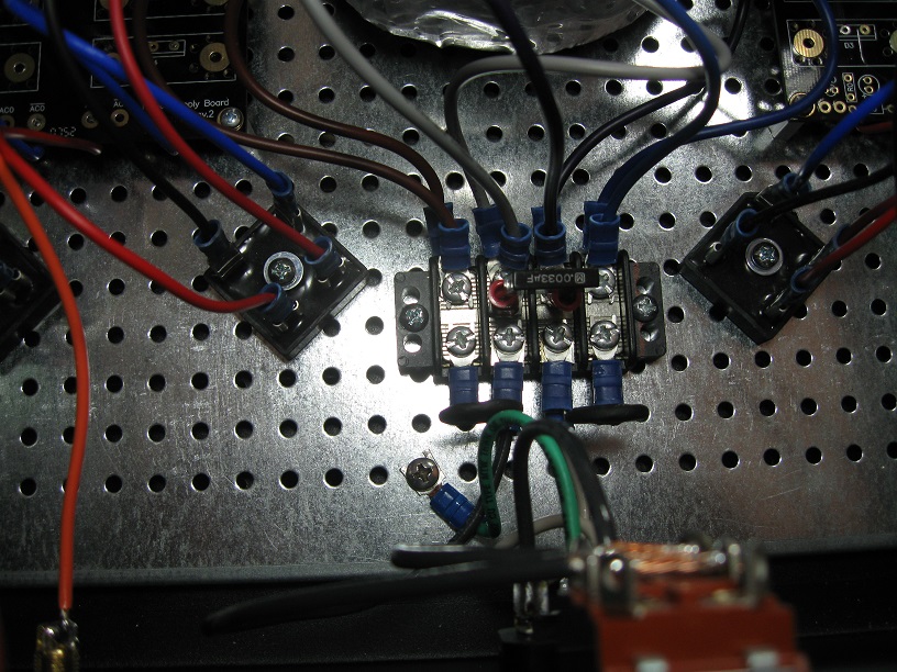
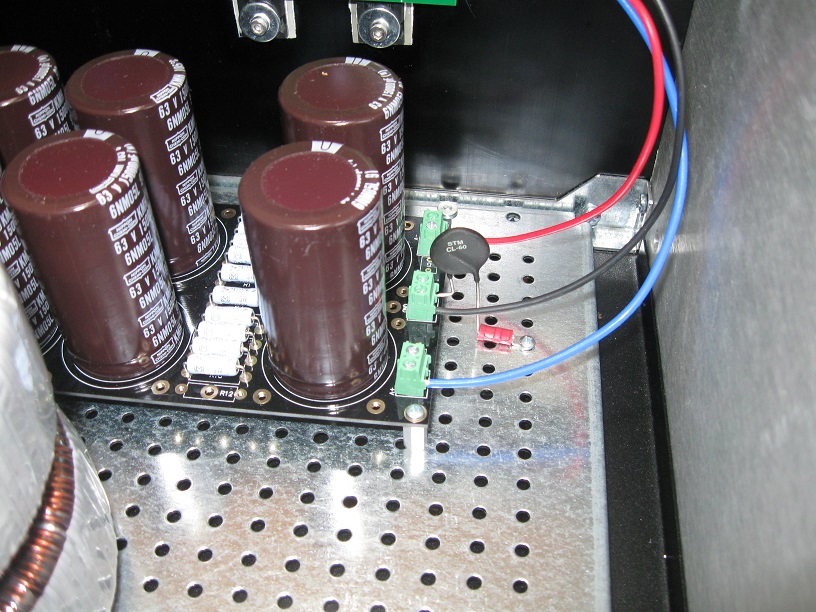
For more details on my Aleph J clone build follow the link https://www.diyaudio.com/forums/pass-labs/224881-aleph-universal-mounting-spec-31.html#post3481260
The third picture shows how the PSU board ground (audio ground) is connected to the chassis using a NTC thermistor.
For more details on my Aleph J clone build follow the link https://www.diyaudio.com/forums/pass-labs/224881-aleph-universal-mounting-spec-31.html#post3481260
Hello,
Some people say dont use it BUT for safety it is best to connect the safety ground or earth directly to the chassis after the power cable has entered the chassis. I think there are even some regulation on how to do it. If i am right one is that you cannot use this connection for anything else.
Do it like Grimberg has shown us.
LONG LONG time ago there was a Nelson Pass design that used a 10 ohm resistor to prevent a ground loop from appearing.
In the link i posted a week ago there are some advices you can use.
Jean Hiraga himself wrote that with big caps and a circuit with low PSRR even the smallest change of '' strategy '' could make a big difference.
Saturday Helmut will give us an update on his power supply modification.
Nilton in Brazil is still waiting for my parcel so it could take until Christmas before his big Monstre will work. A pity he doesnt have any amp in his set that will be a challenge for his new device. But living in Sao Paulo he should be able to find some people willing to give it a try. Of course a le monstre isnt an amp that will work with all speakers. Apogee Duetta probably not but it could be that old quad 55 will shine.
Greetings, Eduard
- Home
- Amplifiers
- Solid State
- Hiraga "Le Monstre"