Hello,
I think the current for the 20 watt should be 1A and for the 30 watt 1,5 A THAT is if you are using the same supply voltages as the original ones!
Of course using a CLC supply with the right choke ( like the ones the French used in some other designs) will give far netter results than CRCRC supply.
LCRC is even better but is a bit hard to achieve considering the high current involved.
2Sadik these caps are 150.000 uF each? I think the big resistor will heat up the caps. I would surely take one cap away on each side and turn it into a CLC supply.
The R or the L coming from the first cap should always ener in the middle of the copper bar and also leave from there going to the circvuits as can be seen in the original Hiraga articles. I think i already posted the correct way to do it.
Greetings, Eduard
Hello,I build the hiraga with Jim's kubota boards, with the intended parts I got a 500ma bias, it is possible to raise it by changing a few resistor values though
I thought you were actually using it with 500 mA but you adjusted the 220 or 440 ohm next to the bias pot to get the right current.
Temperature depends a lot on how it easy the transistor itself can transfer the heat to the sink. In the beginning when there was just the 20 watt only after getting new transistor having better ( c/w value) . The old one become extinct. They were able to make the 30 watt.
Greetings, Eduard
That resistor won't dissipate more than a few watts, no problem, but I would use like three 1.5 ohm resistors and I would use metal film and not wire woundHello,
I think the current for the 20 watt should be 1A and for the 30 watt 1,5 A THAT is if you are using the same supply voltages as the original ones!
Of course using a CLC supply with the right choke ( like the ones the French used in some other designs) will give far netter results than CRCRC supply.
LCRC is even better but is a bit hard to achieve considering the high current involved.
2Sadik these caps are 150.000 uF each? I think the big resistor will heat up the caps. I would surely take one cap away on each side and turn it into a CLC supply.
The R or the L coming from the first cap should always ener in the middle of the copper bar and also leave from there going to the circvuits as can be seen in the original Hiraga articles. I think i already posted the correct way to do it.
Greetings, Eduard
Hello,
I think even of the resistor will dissipate a few watt it will get warm . It will surely not get to warm ( once i had this kind of resistor explode) but caps like to stay cool.
I would surely go for a wirewound resistor, the ones that can be mounted up in the air.
Greetings,Eduard
I think even of the resistor will dissipate a few watt it will get warm . It will surely not get to warm ( once i had this kind of resistor explode) but caps like to stay cool.
I would surely go for a wirewound resistor, the ones that can be mounted up in the air.
Greetings,Eduard
Hello,
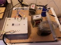
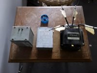
Will be absent untill 26 October. In the photo a choke input power supply used in my 2.1 audio set up for watching movies.
Cheap Philips lab. Quality power transformer.
SMALL high grade 3A diodes ( winner audio lineair test) No need for high currents diodes because of choke input no pulsating currents.
Input choke from Belgian member on this site. One in each leg.
Bleeder resistor.
Second smaller lundahl choke and some Kemet caps.
Greetings,Eduard
Attachments
Hiraga Le Monstre Power Supply
Hi there,
Im a newbie going to build a Le Monstre amp as my very first diy project (I've been thinking about this amplifier for at least 10 years ...)
According to mr Eduard convictions and his earlier demonstrations on this forum; and after watching so many youtube videos that demonstrate advantages of the choke input power supply in reducing ripple compared to RC or CLC fiters, I decided to go with a dual choke input power supply for my Le Monstre.
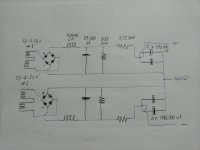
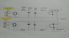
As I have no experience on this business, I kindly would like to have some help from experienced Diyaudio members on how to build this power supply. I make a very amateur drawing inspired in some old Le Monstre power supplies, and would like to be sure that Im in the right way.
Since I hope not to drop the energy in the neighborhood, as well as not electrocute myself before listening to the amplifier ... lol ... I will really appreciate the comments and corrections of the attached diagram.
Greetings!
Nilton
Hi there,
Im a newbie going to build a Le Monstre amp as my very first diy project (I've been thinking about this amplifier for at least 10 years ...)
According to mr Eduard convictions and his earlier demonstrations on this forum; and after watching so many youtube videos that demonstrate advantages of the choke input power supply in reducing ripple compared to RC or CLC fiters, I decided to go with a dual choke input power supply for my Le Monstre.
As I have no experience on this business, I kindly would like to have some help from experienced Diyaudio members on how to build this power supply. I make a very amateur drawing inspired in some old Le Monstre power supplies, and would like to be sure that Im in the right way.
Since I hope not to drop the energy in the neighborhood, as well as not electrocute myself before listening to the amplifier ... lol ... I will really appreciate the comments and corrections of the attached diagram.
Greetings!
Nilton
Attachments

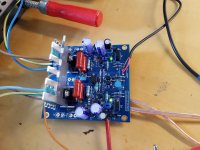
I just tried rectifier/choke/capacitor/resistor/capacitor. All together 2.7 F capacitors + large MKP (300 µF) each mono block, 15 VAC, around 500VA transformer (2x). PCB from Jims Audio, all resistors Shinko, original Transistors, everything well matched but the power transistors. 11,5 v, 0,75 A.
The change to rectifier / choke is significant different in sound, but I need some days of listening to describe what has happend.
I once tried Super Cappa, 36 F each block, sounds very good, very palpable, but I had irritating differences in voltage +/-, so I skipped this iteration.
This amplifier is a nice playground, I own it for more than 20 years but didn't use it all the time.
...All together 2.7 F capacitors ... each mono block ...around 500VA transformer
...I once tried Super Cappa, 36 F each block, sounds very good, very palpable,
This amplifier is a nice playground, I own it for more than 20 years but didn't use it all the time.
@Helmut.
Congrats with your set-up.
In the same time I had:
+ One central PSU with (2x2x5x300kmicro) & 12Vdc
+ 2x4 "Monster" amp ...
+ With Kaneda: pre-amp & actif X-over 18dB/oct ..... 2x4 way .
My "Octo-pus" amp ... & 4 way full horn concept.
It was (is) music .... in heaven
Allez, salukes.
Karel
24vac is pretty high, I ran around 16vdc....
Hi Konst,
Yes, Vac is a bit high, but after choke and resitors, it is expected to drop to aprox. 13,5 - 14vdc...
PCB can run up to 15V, with 15W maximum output.
Concerning the connections, especially the last 4 180.000uF caps, do you think it is ok?
Tks
Nilton
Hello,
Small message from sunny beach!
IF you make a change to choke input. There are surely some things you should know.
Critical inductance
right kind of choke so the right value.
Nilton is using one that can be used for le monstre.
My friend is using the same one in a stereo CLC supply in a 20 Hiraga with 1A running on each side.
If you wanna use a true choke input you will need a transformer with a higher ac output.
If DC output to the circuit is higher than AC going into the rectifier it is surely not a choke input.
I must have some vintage French chokes that can take 1,3A 100mH that could be used in a double mono set up. They will be cheaper than Lundahl. They could be used for a mono le monstre with choke input.
But Lundahl offers some model that will better suit your needs .
@ Helmut if you start with 15 volt ac and end up with 11,5 volt dc you probably created a choke input. BUT to truly make a good test you should change your transformer ( can be smaller VA with choke input) so you will get the same DC voltage on the circuit as before.
Greetings, eduard
Hello,
@Nilton your drawing is correct.
BUT what is very important is to realize is that the hard work is done by transformer, rectifier, choke and first cap( with 300ohm attached).
Probably it will be possible to connect the bridge directly to the transformer AC terminals ( it could need a little heatsink but i am have been running a 3A sbyv in choke input with 1A current for a year now) Probably you can touch your bigger rectifier without any heatsink!)
So the first elements working hard you should keep the wires between them as short as possible. 2 inches is better than 6 inches.
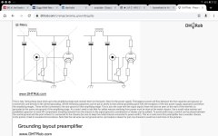
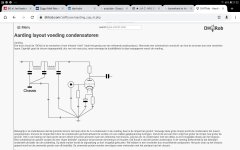
Take a look at the two attachments. It is a single rail supply but the ideas are the same.
With the Hiraga design current running is bigger so the way to connect can be even more important. Connecting the caps with copper bars is nice. BUT you have to know where to connect the wires to these bars. It has been said before with copies from Hiraga article but people still do it wrong.
Same like using a 1000VA transformer , a big rectifier and then a few beer can caps. Sure, you can get a rectifier that will survive but it will result in big , very big charging pulses that will end up messing up your sound. That is why they start using a CRC or CLC filter . Here you can carefully chose the seize of the first cap. ( my friends 20 watt Hiraga uses 47.000uF)
WITH choke input there will be no charging pulses.
In this link there is some useful info.
http://hifisonix.com/wordpress/wp-content/uploads/2019/02/Ground-Loops.pdf
@Nilton your drawing is correct.
BUT what is very important is to realize is that the hard work is done by transformer, rectifier, choke and first cap( with 300ohm attached).
Probably it will be possible to connect the bridge directly to the transformer AC terminals ( it could need a little heatsink but i am have been running a 3A sbyv in choke input with 1A current for a year now) Probably you can touch your bigger rectifier without any heatsink!)
So the first elements working hard you should keep the wires between them as short as possible. 2 inches is better than 6 inches.
Take a look at the two attachments. It is a single rail supply but the ideas are the same.
With the Hiraga design current running is bigger so the way to connect can be even more important. Connecting the caps with copper bars is nice. BUT you have to know where to connect the wires to these bars. It has been said before with copies from Hiraga article but people still do it wrong.
Same like using a 1000VA transformer , a big rectifier and then a few beer can caps. Sure, you can get a rectifier that will survive but it will result in big , very big charging pulses that will end up messing up your sound. That is why they start using a CRC or CLC filter . Here you can carefully chose the seize of the first cap. ( my friends 20 watt Hiraga uses 47.000uF)
WITH choke input there will be no charging pulses.
In this link there is some useful info.
http://hifisonix.com/wordpress/wp-content/uploads/2019/02/Ground-Loops.pdf
Attachments
Hello Eduard,
in the older configuration I used CRC with 8 Ohm, I was always in the region of about 12 V. Frankly speaking, I use the Choke to go down with the voltage, in each supply I use 4 capacitors with 0.5 f and only 15 V allowed voltage, may be they are good for 17 or even 20 V, but I sleep better with a max. of 12 V on them.
My chokes are bought used, large core and what I can see, high diameter of the wire, I estimate it to 2 mm. I don't know the inductivity nor if they really have an air gap. But they work, don't make any noise or get hot, not even warm.
Hello ,
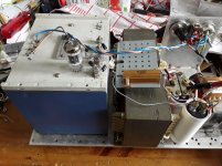
In the photo you can see my French chokes they are made for DC as indicated.
The blue one is used used in a power supply filter on the 230 volt side.
The big one is an R core 20 mH with double wiring same function like the blue one but for BIG current. If i remember well i used it once for choke input and it got hot. So it was surely saturating.
Maybe you can make a simple test set up in a CLC configuration. Then make a load with a high power resistor so there will be 1A or so going through the choke. Then you can calculate the dc resistance of the choke.
If it is 0,5 ohm you can make another set up.
One RC with a 0,5 ohm resistor and 1A current as load.
One LC with 1A current as load.
If LC is working like a choke input the voltage on the cap will be much lower.
Because the voltage is lower the high power resistor much be lower in value to get 1A running too. Then voltage will drop a little more.
A 500.000 uF after the rectifier even with choke input is to big i think. Better get something like 47000uF and make it LCRC R something like 0,2.....0,5 ohm.
Would be nice to have your chokes checked for mH at the actual current you are using.
Once i had a 68.000 uF 25 volt input cap go BAD after a year of use with 24 volts dc. Remember the input cap must work hard so better have a bigger safety margin. The last caps '' feeding '' the circuit can be 15 volt if the actual voltage is 12 volt BUT if one of the circuit go bad and you will not have as much voltage drop across the choke or the resistor it can go boom. A good cap will have a kind of safety '' opening '' so it will not explode but start to make a ssssss noise, like a water kettle.
That is why, my Brazilian friend Nilton uses a 300 ohm resistor to be sure there is a minimum current running ALL the time. If you know the mH value you can calculate the value that resistor needs to be.
Caps nowadays arent that expensive anymore and they have gotten much smaller. I like the Kemet caps Nilton is using.
Greetings, Eduard
Attachments
Hello,
NOT a lot of input from people who actually own a Hiraga design now and willing to try some ideas given her.
I have my Belgian friend going from clc to a bigger choke and new Kemet caps soon for his 20 watt Hiraga.
There is a vietnamese friend choke input ll2733 for a single ended Nelson pass design.
Up to you now.
Greetings,Eduard
Well I am going to reconfigure my Monstre, I built it with the croatian PSU board, but I am not happy with the size of the tracks as the drop seems to be too high and the diodes are much hotter than they should be (imho). I am going to wire it discretely with a 2x 47k .3ohm 8x47k, crc arrangement and see what happens.
Further I am going to try a choke implementation as a second step, but I am still thinking about how to do that with the components I have available, thinking I will try various transformer primaries/secondaries see what comes out (I have several pairs of trafo's in various VA ratings). I will measure with my ears and report what I find.
Further I am going to try a choke implementation as a second step, but I am still thinking about how to do that with the components I have available, thinking I will try various transformer primaries/secondaries see what comes out (I have several pairs of trafo's in various VA ratings). I will measure with my ears and report what I find.
- Home
- Amplifiers
- Solid State
- Hiraga "Le Monstre"