Here is a first amplifier build of my le monster on the cheap (I am a beginner in building amps so don't be too hard on me):
View attachment 408990
View attachment 408991
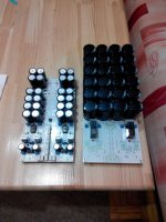
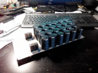
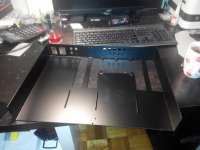
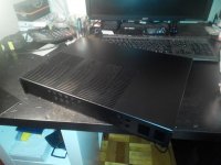
I had two RS switch mode power supplies (+/-12V, 1.8A) lying around and had found not too expensive preassembled old version boards from diy-audio-world on eBay. The boards use some changed components (power resistors e.g. would be better if non-inductive) and use K246_GR2k / L4f transistors and tip3055 / tip2955 output transistors. The case from modushop was expensive but is nice and has room for a second channel if I add a tweeter to my frugal horn speaker, or decide to upgrade to amore powerful pass f5 build.
The sound of the smps le monster is pretty good, comparing it to a miniwatt 2.5Watt single ended tube amp, I am happy, my le monster might have slightly more attack in the highs. There is slight hum in the high sensitivity foster drivers, but not too bad, and I think I can improve shielding from the sips (funny thing is that hum is reduced when touching the shield of cinch input). However I have slight problems adjusting the dc offset for one channel, as it fluctuates and is super sensitive on the potentiometer setting. This channel also is slightly louder. Both power supplies deliver stable +/-12.2V and the bias current is a perfectly stable 0.6A for each transistor.
Does anyone have tips how to reduce the amplification of the louder channel and why the balancing in this channel might be trickier?
Thanks, Stefan
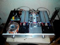
Why have you mounted the output devices at one end of the heatsink, they would shed more heat if you mounted them in the centre.
The case has four seperate heatsinks (two on each side), so I have mounted the transistors exactly at the center of the back heatsinks to keep the signal path short - and even now I get some noise from the smps in the circuit. The back heatsink is plenty big for the dissipation, and indeed one can just barely detect that the heatsink is warmer than ambient.
Any tips for reducing noise from the smps? And one of the channels is tricky to balance, and the dc offset starts at 10 volts during warm up, which is not healthy for the speaker - which parts could one check to make this channel be as perfectly offset balanced as the other?
Thanks for any tips.
Any tips for reducing noise from the smps? And one of the channels is tricky to balance, and the dc offset starts at 10 volts during warm up, which is not healthy for the speaker - which parts could one check to make this channel be as perfectly offset balanced as the other?
Thanks for any tips.
So, pursuant to another post, I am planning to put a Hiraga in my Hafler 220 chassis. Right now, I'm thinking of Jims Audio boards/parts (cheap and easy is the goal), and a capacitance multiplier based on Rod Elliot's circuit. Some questions:
1) Any recommendations for TO-3 devices for the outputs? The Hafler heatsinks are made for 'em.
2) I'm thinking an Antek 300va 15V or 16V transformer will do the trick. Does that seem about right?
3) The 15V is $5 more as it has a shield between the primary and secondary. Do you think that matters in this application?
4) It looks like if one was going to buy a fancier caps for the capacitance multiplier, the 1000uf at the back matters quite a bit more than the 10000uf at the front. Sense or nonsense?
5) Finally, I'd love to see pics of grounding schemes on the capacitance multipliers. Elliot makes it sound like it is a pretty big deal, so I want to plan it with enough copper. But doing it on a bar or plate sounds like a pain, so if I can get by with a big bare wire. . . (Just holler if you think these last two or three belong over in the PS forum, but there seems to have been plenty of relevant talk earlier in the thread.)
Paul
Don't do it.Here is a first amplifier build of my le monster on the cheap (I am a beginner in building amps so don't be too hard on me):
View attachment 408990
View attachment 408991
I had two RS switch mode power supplies (+/-12V, 1.8A) lying around and had found not too expensive preassembled old version boards from diy-audio-world on eBay. The boards use some changed components (power resistors e.g. would be better if non-inductive) and use K246_GR2k / L4f transistors and tip3055 / tip2955 output transistors. The case from modushop was expensive but is nice and has room for a second channel if I add a tweeter to my frugal horn speaker, or decide to upgrade to amore powerful pass f5 build.
The sound of the smps le monster is pretty good, comparing it to a miniwatt 2.5Watt single ended tube amp, I am happy, my le monster might have slightly more attack in the highs. There is slight hum in the high sensitivity foster drivers, but not too bad, and I think I can improve shielding from the sips (funny thing is that hum is reduced when touching the shield of cinch input). However I have slight problems adjusting the dc offset for one channel, as it fluctuates and is super sensitive on the potentiometer setting. This channel also is slightly louder. Both power supplies deliver stable +/-12.2V and the bias current is a perfectly stable 0.6A for each transistor.
Does anyone have tips how to reduce the amplification of the louder channel and why the balancing in this channel might be trickier?
Thanks, Stefan
Transistors must be on the centre.
Nice enclosure!
Please can you say the supplier and the price?
Regards.
If I understood you right:So, pursuant to another post, I am planning to put a Hiraga in my Hafler 220 chassis. Right now, I'm thinking of Jims Audio boards/parts (cheap and easy is the goal), and a capacitance multiplier based on Rod Elliot's circuit. Some questions:
1) Any recommendations for TO-3 devices for the outputs? The Hafler heatsinks are made for 'em.
2) I'm thinking an Antek 300va 15V or 16V transformer will do the trick. Does that seem about right?
3) The 15V is $5 more as it has a shield between the primary and secondary. Do you think that matters in this application?
4) It looks like if one was going to buy a fancier caps for the capacitance multiplier, the 1000uf at the back matters quite a bit more than the 10000uf at the front. Sense or nonsense?
5) Finally, I'd love to see pics of grounding schemes on the capacitance multipliers. Elliot makes it sound like it is a pretty big deal, so I want to plan it with enough copper. But doing it on a bar or plate sounds like a pain, so if I can get by with a big bare wire. . . (Just holler if you think these last two or three belong over in the PS forum, but there seems to have been plenty of relevant talk earlier in the thread.)
Paul
a) I don't know who is Jim's Audio, I had made Le Monstre 8W on my own PCB test variant with noise level: -120 dB on 50 Hz and -127 dB on 100 Hz.
1) I using MJL21196+MJL21195, but I want to buy MJ15024+MJ15025 (TO-3) becuase they a little better than MJL21196+95 and MJL21194+93. The heatsink's area must to be 50...60 cm^2 per 1W (for +-13,7V and Ic=1,25A it will be 1500 cm^2 per channel).
2) The better quality you can to reach with ACB in buffer (2x12V 1,2...7,2A*h), but power supply after R in CRC-filter +-13,5V..+-13,8V.
3) The transformer with shield - is good idea. But it must have low induction (1,1T maximum, optimal 0,8T).
4) Size of capicotors you oneself define. My PCB have 0,8F (24x33000uF). Filter construction: 66000uF+1 om (20W)+132000uF in a shoulder on the channel.
5) I don't think, that using plates and "big wire" - good idea. Power unit and amplifier unit must to be on joint PCB with Dual Channel. The best of all, if relay regulator of volume will be on this PCB too.
And so: on a PCB both channels with diode bridges and condenser filters have to settle down, in an ideal on the same PCB to place the relay regulator of volume. The PCB has to have thickness of a foil of 105 microns covered with immersion gold.
p/s: having listened to a great number of different amplifiers, I think that Le Monstre the best amplifier in the world.
")
p/s2: Sorry for my english
So, pursuant to another post, I am planning to put a Hiraga in my Hafler 220 chassis. Right now, I'm thinking of Jims Audio boards/parts (cheap and easy is the goal), and a capacitance multiplier based on Rod Elliot's circuit. Some questions:
1) Any recommendations for TO-3 devices for the outputs? The Hafler heatsinks are made for 'em.
2) I'm thinking an Antek 300va 15V or 16V transformer will do the trick. Does that seem about right?
3) The 15V is $5 more as it has a shield between the primary and secondary. Do you think that matters in this application?
4) It looks like if one was going to buy a fancier caps for the capacitance multiplier, the 1000uf at the back matters quite a bit more than the 10000uf at the front. Sense or nonsense?
5) Finally, I'd love to see pics of grounding schemes on the capacitance multipliers. Elliot makes it sound like it is a pretty big deal, so I want to plan it with enough copper. But doing it on a bar or plate sounds like a pain, so if I can get by with a big bare wire. . . (Just holler if you think these last two or three belong over in the PS forum, but there seems to have been plenty of relevant talk earlier in the thread.)
Paul
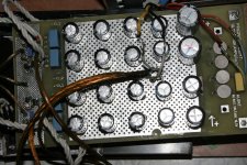
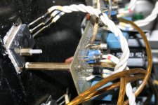
PCB by Alexey Koval (2 photo) and my PCB "1st test board" with 0,12F (2 photo)
Attachments
I forgot to write about BJT and JFET. BJT: BC550C Philips+BC560C On Semi, JFET: KP303I+KP103K (gold), Drivers: 2SD756+2SB716 Hitachi. Out: MJL21196+MJL21195 ON Semi.So, pursuant to another post, I am planning to put a Hiraga in my Hafler 220 chassis. Right now, I'm thinking of Jims Audio boards/parts (cheap and easy is the goal), and a capacitance multiplier based on Rod Elliot's circuit. Some questions:
1) Any recommendations for TO-3 devices for the outputs? The Hafler heatsinks are made for 'em.
2) I'm thinking an Antek 300va 15V or 16V transformer will do the trick. Does that seem about right?
3) The 15V is $5 more as it has a shield between the primary and secondary. Do you think that matters in this application?
4) It looks like if one was going to buy a fancier caps for the capacitance multiplier, the 1000uf at the back matters quite a bit more than the 10000uf at the front. Sense or nonsense?
5) Finally, I'd love to see pics of grounding schemes on the capacitance multipliers. Elliot makes it sound like it is a pretty big deal, so I want to plan it with enough copper. But doing it on a bar or plate sounds like a pain, so if I can get by with a big bare wire. . . (Just holler if you think these last two or three belong over in the PS forum, but there seems to have been plenty of relevant talk earlier in the thread.)
Paul
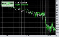
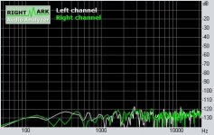
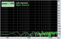
My PCB RMAA Le Monstre 8W 0,8F own noise graphics (screenshots in "realtime")
(Open input, closed input, touch to open input
)Attachments
Last edited:
Don't do it.
Transistors must be on the centre.
Nice enclosure!
Please can you say the supplier and the price?
Regards.
The enclosure is from modu and costs 170 €.
Here is a first amplifier build of my le monster on the cheap (I am a beginner in building amps so don't be too hard on me):
View attachment 408990
View attachment 408991
I had two RS switch mode power supplies (+/-12V, 1.8A) lying around and had found not too expensive preassembled old version boards from diy-audio-world on eBay. The boards use some changed components (power resistors e.g. would be better if non-inductive) and use K246_GR2k / L4f transistors and tip3055 / tip2955 output transistors. The case from modushop was expensive but is nice and has room for a second channel if I add a tweeter to my frugal horn speaker, or decide to upgrade to amore powerful pass f5 build.
The sound of the smps le monster is pretty good, comparing it to a miniwatt 2.5Watt single ended tube amp, I am happy, my le monster might have slightly more attack in the highs. There is slight hum in the high sensitivity foster drivers, but not too bad, and I think I can improve shielding from the sips (funny thing is that hum is reduced when touching the shield of cinch input). However I have slight problems adjusting the dc offset for one channel, as it fluctuates and is super sensitive on the potentiometer setting. This channel also is slightly louder. Both power supplies deliver stable +/-12.2V and the bias current is a perfectly stable 0.6A for each transistor.
Does anyone have tips how to reduce the amplification of the louder channel and why the balancing in this channel might be trickier?
Thanks, Stefan
Don't use impulse power supplies in final version of amplifier, only in test version.
TIP2955/TIP3055 TO-220 from ST - so badly BJT. If you want to use low cost BJT in output - I recommending "to look" on KEC 2SD718+2SB688.
Yes, sometimes it have a little problems with DC out, but it's not fatal, you can to change trimmer 100 om on 220 om or 470 om, but Ic will be smaller, you can play with risistors in collectors of output (1 om in stock) and resistors in small BJT collectors (1k in stock).
If DC out 100 mV or less - this is not problem.
Use the SMPS for test only. Ultimately it will sound far better with a transformer based linear CRC supply.
Yes!
Toroidal transformer -> CRC (+ACB in Buffer) Thanks my friend .The enclosure is from modu and costs 170 €.
Can you post the type of this?
Thimios
Last edited:
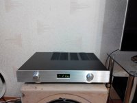
Nice work!my Le class. The enclosure 70 €.
Is this pcb by Alexey Koval?
Where i can find this pcb?
What about volume controller?
Regards .
Thimios.
Nice work!
Is this pcb by Alexey Koval?
Where i can find this pcb?
What about volume controller?
Regards .
Thimios.
Alexey Koval are "Lensyc" (he incuded his amplifier case in post 953), you can to whire to him about this "Dual Channel with relay volume controller" PCB.
Last edited:
Nice work!
Is this pcb by Alexey Koval?
Where i can find this pcb?
What about volume controller?
Regards .
Thimios.
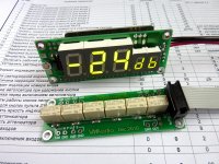
Relay attenuator (it could have 64 or 128 steps regulation of volume per channel) doesn't bring any distortions in a signal, unlike potentiometers as ALPS and other.
Attachments
Nice work!
Is this pcb by Alexey Koval?
Where i can find this pcb?
What about volume controller?
Regards .
Thimios.
This relay attenuator has been constructed by Maxim Volobuev.
Last edited:
A decent pot will introduce no more sound to the signal than a ladder attenuator or relay pot.
As for distortion, no pot should add any distortion.
The only real benefit of a ladder pot is the matching between the channels.
The only real benefit of a relay pot is the number of steps (resolution).
As for distortion, no pot should add any distortion.
The only real benefit of a ladder pot is the matching between the channels.
The only real benefit of a relay pot is the number of steps (resolution).
A decent pot will introduce no more sound to the signal than a ladder attenuator or relay pot.
As for distortion, no pot should add any distortion.
The only real benefit of a ladder pot is the matching between the channels.
The only real benefit of a relay pot is the number of steps (resolution).
Relay attenuator much better, than potentiometer, the sound doesn't differ from the through channel. With potentiometer (ALPS RK27) falldown details of sound, it's make the sound "dullness and wattage".
And price of relay attenuator (simle complectation) is twice lower, than at RK27.
Price of RA - 30$
Price of RK27 - 65$.
Utter rubbish, try a "decent" pot, not a ten cent pot.
A pot in a set position is but two resistors co-joined at the centre.
You are trying to tell us that 100 crappy relay contacts will improve the sound quality - I think not. You've also got to consider the considerable PCB tracks that will expose the signal to the elements too.
A pot in a set position is but two resistors co-joined at the centre.
You are trying to tell us that 100 crappy relay contacts will improve the sound quality - I think not. You've also got to consider the considerable PCB tracks that will expose the signal to the elements too.
Last edited:
- Home
- Amplifiers
- Solid State
- Hiraga "Le Monstre"