Just a comment on Hiraga's and the PSU. The way the amp output stage is designed makes the PSRR really low, so it pays off to invest in the PSU! I've had a LeClasse A 20 W which I converted to battery PSU (sealed lead-acid). That was a lot better than the classic tranformer-bridge-large capacitors thing, but it demanded bypass caps. I used 1000 uF electrolytics and (I think) 10 uF PP film caps.
If using lead-acid batteries, its possible to constant-charge the batteries using the regular PSU. Just be sure to put in some series resistance between the PSU and the batteries to avoid over-charge.
If using lead-acid batteries, its possible to constant-charge the batteries using the regular PSU. Just be sure to put in some series resistance between the PSU and the batteries to avoid over-charge.
")
Re: testing le monstre
Take care about batteries though. Just to summarize the previous said:
1. you need many AH batteries for long playing music (much more than the theoretical value)
2. Buy only deep cycle batteries if operate on battery only mode, which will allow them to discharce quite a lot without limit their life. (car batteries are not good for battery ONLY operation)
3. you need these small bypass caps combinations
bluevas said:Thank you for the comment, I will use Dan power supply using LM338 for the following steps and prepare to buy a car battery also
Regards,
Take care about batteries though. Just to summarize the previous said:
1. you need many AH batteries for long playing music (much more than the theoretical value)
2. Buy only deep cycle batteries if operate on battery only mode, which will allow them to discharce quite a lot without limit their life. (car batteries are not good for battery ONLY operation)
3. you need these small bypass caps combinations
Aksa would you say a word about teflon capacitors for bypassing in conjunction with silver/oil Mundorf? I know there is another thread on this but I would like just a quick review.
Teflon has excellent dielectric properties (the best one after air I think)
see these http://cgi.ebay.com/0-47uF-200V-tef...304745&_trksid=p3286.c0.m14&_trkparms=72:1205|66%3A4|65%3A12|39%3A1|240%3A1318|301%3A1|293%3A1|294%3A200
Teflon has excellent dielectric properties (the best one after air I think)
see these http://cgi.ebay.com/0-47uF-200V-tef...304745&_trksid=p3286.c0.m14&_trkparms=72:1205|66%3A4|65%3A12|39%3A1|240%3A1318|301%3A1|293%3A1|294%3A200
I can't say much about teflon used as bypass, Neazoi, only for input caps on audio amplifiers. For bypass I generally try to use film/foil polypropylene since it's much cheaper than teflon.
I have used all kinds of input caps on power amps, and concluded that regrettably the most transparent is the teflon. I use sonicap, but I've no reason to think other brands are bad, and I know the Russian teflons are pretty cheap.
My feeling is that three things are required; rapid charge migration across the electrodes, ruling out metallised constructions; low dielectric constant, and low dielectric absorption, to eliiminate time smear distortion. This makes good caps very bulky.
Energy is stored in a cap by mechanical stress of the dielectric since opposite charge attracts, compressing the dielectric. This also indicates that the youngs modulus of the dielectric could be important too, though I've not seen studies on this. A low dielectric constant would reduce the stresses, possibly enhancing compressive linearity.
Many caps, even electros, are excellent if a bias voltage is placed across the cap. There is merit in designing for this bias, as it means lower cost for the caps, and it is a feature of tube designs. But in applications where very low voltages appear across the cap, such as C1 in a Lin topology where it's typically 0.1 volt, very expensive caps are needed for the utmost transparency, if that is what you are looking for.
Balanced against this is the certain knowledge that not everyone likes the same thing. Some like tubes, some like SS, after all.
Cheers,
Hugh
AKSA said:Caps are needed for the batteries because the series impedance of the source rises rapidly after about 10KHz.
However, you don't need all that much, about 1000uF would be fine as long as it's good quality capacitance.
Hugh
Hugh,
I've measured SLA's OP Z and they are pretty flat to well above 10kHz.
This was quite some time ago but I do recall they went to around
200kHz before significant rise in impedance. These were 12V 2.2AH
gel cells.
So only a local bypass cap on amplifier PCB is necessary and it
wouldn't have to be that large.
Neazoi, not osure if this was mentioned but you -MUST- fuse the
batteries as close to battery as possible. They have HUGE
instantaneous current output and can easily cause a fire in the
event of a short.
cheers
Terry
Output transistors
I am pretty much a beginner in diy audio, having made several projects over the last year and a half or so. These include two versions of Le Monstre, both using the same (external) PSU - a capacitance multiplier based on the circuit from the ESP site. (This puts out about 14V under load, which is a little higher than ideal, perhaps, but it seems to me to be within the reasonable range.)
When I did the first version I failed to get the right jfets, or any of the Toshiba subsitutes. In the end I found 2N5462, and an N-channel equivalent (not quite sure of the number without opening up the amp, but not 2N5457...) The rest of the circuit used the modern equivalents given in
http://www.kk-pcb.com/hiraga.html
that is, TIP2955 and 3055, with BC550 and 560 for the other bipolars. It took a good while to get this working, but I was very pleased with it in the end. (And it still sounds v. good.)
Some time later, I decided to make another, this time importing 1% metal film resistors and so forth, to see if they really produced an audible difference. At first I used 2N5457 and 5460 for the jfets, since Mouser didn't have the Toshibas (no surprise there, I learned later...) After reading around on the web I decided on 2SC5200 and 2SA1943 as output transistors, which I sourced locally. (Still used BC550 and 560 for the rest). The amp worked first time, the main differences from the first being that it was louder, and showed a little more noise (disappointingly...).
Much later, I decided to build an F5 (there is a thread up on the Pass Labs forum with photos, if anyone is interested) and imported the Toshiba jfets. So, since I was very happy with the F5 I altered the second Monstre by putting the "right" jfets in - which made little difference, apparently. (I don't have much inthe way of measuring equipment, so this a purely subjective listening test...)
Some time later something in the second amp went wrong, and I had very high levels of noise, making it unusable. (Blown jfets, maybe?) So the last couple of nights I have completely rebuilt it, reusing the 2SC5200 and 2SA1943, but everything else new. (I also switched to 2SA970 and 2SC2240 after the jfets and BC639 and 640 as drivers - this was from looking at a schematic someone posted earlier on this thread, although I couldn't find the 2SA872 and 2SC1775 recommended.)
So here are a couple of things I would like to understand.
1. The second (now third) amp has a slightly more appealing sound than the first, even though it has more noise. Why is there more noise? (there is also some hum, which can doubtless be improved through better grounding - I am asking about hiss, or static). Some is doubtless due to my building skills (!), but is it possible the output trannies or choice of drivers are to blame? The output trannies are sourced locally, so are possibly fake, although I have no (other) reason to suspect this.
2. The 2SC5200 and 2SA1943 are (obviously) much more powerful transistors than necessary for this design. I have seen several recommendations for others (TIP35A and 36A, TIP2955 and 3055, MJE15030 and 15031...) but is there any consensus on what's best, and to what extent the driver must be chosen to match the output trans.?
3. Why is the second amp so loud? Not only is it louder than the first Le Monstre, it compares with my F5, which makes no sense at all... Can this be solely due to the choice of output trans.? The bias is at 520mA, which is right in the recommended range - is htis perhaps insufficient for these output transistors?
Well, I'd be very grateful for any suggestions or other input.
Cheers
Nigel
Re: Output transistors
Hi Nigel,
As a suggestion after briefly reading the datasheet the 2N5462 is not an equivalent in terms of noise etc.
for the output stage on the le monstre it is not ideal to use the 2SC5200/2SA1943 the Cob is a bit higher than desirable for this amp and the power rating is unnecessary.
I also think the input transistor selection will help if you can source the correct transistors. I have some of the required transistors if you are interested send me a private message so I dont annoy people on here.
-Dan
njepitt said:I am pretty much a beginner in diy audio, having made several projects over the last year and a half or so. These include two versions of Le Monstre, both using the same (external) PSU - a capacitance multiplier based on the circuit from the ESP site. (This puts out about 14V under load, which is a little higher than ideal, perhaps, but it seems to me to be within the reasonable range.)
When I did the first version I failed to get the right jfets, or any of the Toshiba subsitutes. In the end I found 2N5462, and an N-channel equivalent (not quite sure of the number without opening up the amp, but not 2N5457...) The rest of the circuit used the modern equivalents given in
http://www.kk-pcb.com/hiraga.html
that is, TIP2955 and 3055, with BC550 and 560 for the other bipolars. It took a good while to get this working, but I was very pleased with it in the end. (And it still sounds v. good.)
Some time later, I decided to make another, this time importing 1% metal film resistors and so forth, to see if they really produced an audible difference. At first I used 2N5457 and 5460 for the jfets, since Mouser didn't have the Toshibas (no surprise there, I learned later...) After reading around on the web I decided on 2SC5200 and 2SA1943 as output transistors, which I sourced locally. (Still used BC550 and 560 for the rest). The amp worked first time, the main differences from the first being that it was louder, and showed a little more noise (disappointingly...).
Much later, I decided to build an F5 (there is a thread up on the Pass Labs forum with photos, if anyone is interested) and imported the Toshiba jfets. So, since I was very happy with the F5 I altered the second Monstre by putting the "right" jfets in - which made little difference, apparently. (I don't have much inthe way of measuring equipment, so this a purely subjective listening test...)
Some time later something in the second amp went wrong, and I had very high levels of noise, making it unusable. (Blown jfets, maybe?) So the last couple of nights I have completely rebuilt it, reusing the 2SC5200 and 2SA1943, but everything else new. (I also switched to 2SA970 and 2SC2240 after the jfets and BC639 and 640 as drivers - this was from looking at a schematic someone posted earlier on this thread, although I couldn't find the 2SA872 and 2SC1775 recommended.)
So here are a couple of things I would like to understand.
1. The second (now third) amp has a slightly more appealing sound than the first, even though it has more noise. Why is there more noise? (there is also some hum, which can doubtless be improved through better grounding - I am asking about hiss, or static). Some is doubtless due to my building skills (!), but is it possible the output trannies or choice of drivers are to blame? The output trannies are sourced locally, so are possibly fake, although I have no (other) reason to suspect this.
2. The 2SC5200 and 2SA1943 are (obviously) much more powerful transistors than necessary for this design. I have seen several recommendations for others (TIP35A and 36A, TIP2955 and 3055, MJE15030 and 15031...) but is there any consensus on what's best, and to what extent the driver must be chosen to match the output trans.?
3. Why is the second amp so loud? Not only is it louder than the first Le Monstre, it compares with my F5, which makes no sense at all... Can this be solely due to the choice of output trans.? The bias is at 520mA, which is right in the recommended range - is htis perhaps insufficient for these output transistors?
Well, I'd be very grateful for any suggestions or other input.
Cheers
Nigel
Hi Nigel,
As a suggestion after briefly reading the datasheet the 2N5462 is not an equivalent in terms of noise etc.
for the output stage on the le monstre it is not ideal to use the 2SC5200/2SA1943 the Cob is a bit higher than desirable for this amp and the power rating is unnecessary.
I also think the input transistor selection will help if you can source the correct transistors. I have some of the required transistors if you are interested send me a private message so I dont annoy people on here.
-Dan
Hi Dan,
Yes, I realised the 2N5462 wasn't ideal - I used it in the first version simply because it was what I could get my hands on. Now that I have 2SK170 and 2SJ74 (BL grade) I am using these in the second (now third) version.
Since I posted I have also isolated another possible problem. The trimpot I am using is 100R, which according to some posts above is correct for the Y grade jfets, but too low for the BL grade (which have higher Idss...). So I am going to pop in two fixed resistors on either side of the trimpot to see what difference this makes. (I am guessing at 100 to 180R on each side to give a total of 300 to 460 R on the trimpot).
I am a little confused by your remark about Cob of the Toshibas. The datasheet for the 2SB754 (which is the original device) gives typ. 300pF, whereas the 2SC5200 shows typ. 200pF... While out component shopping I picked up two pairs of MJW3281/1302 to try in place of the 2SC5200/1943, but I see from the datasheet that their Cob is higher still (max 600pF is given). Worth trying? (You are certainly correct that the power rating of the 2SC5200/2SA1943 is far higher than necesssary here. I used them because I had them....)
I'll send you a PM about your original transistors.
Cheers
Nigel
I switched a few things around yesterday. First I altered the trimpot as I described two posts above, putting two 180R on either side to make a 460R trimpot. This required messing around with the bias resistors to get things right again. I also switched the output transistors to the MJW3281/1302. These changes solved the gross problem of noise (although this could stil be improved) but the sound still isn't right.
For one thing, it's too loud... I know that sounds a little crazy, but the amp is for use in a very small space, and the volume control on the preamp (B1 buffer passive) is so near the bottom it's difficult to adjust. It also has a hard, or harsh sound, as though something inside is straining. I have nothing to measure THD or anything like that, but my guess is that the output transistors are providing more gain than necessary, but not of a very high quality because there operating in the wrong range. Or something like that... can anyone explain? Maybe the problem is with earlier parts of the circuit?
I think i'll try reducing the 180Rs on the trimpot. If I put something like 100R on either side instead what would be the effect? (obviously I'd have to alter the bias accordingly.)
Anyone have a recommendation for transistors? I keep coming back to theidea that I have chosen output transistors poorly. (Maybe TIP2955/3055 like on the first one?)
Dan: I tried sending you a PM but the system wouldn't let me. If you send a blank e-mail to me I'll reply to it.
Cheers
Nigel
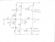
OK, here's a drawing of the circuit I'm using. I didn't put on the values of the bias resistors, since I'm using trimpots for these (at least for the time being). These are adjusted to give 550mA bias, as the Monstre articles recommend. (Although I suppose the recommended value depends on the output transistors too, right?).
I don't use PCBs (at least not yet), all done p2p.
It's not too hard to reduce the resistors on either side of the trimpot (which would reduce it form 460R to, say, 300R). What do you think?
Cheers
Nigel
I don't use PCBs (at least not yet), all done p2p.
It's not too hard to reduce the resistors on either side of the trimpot (which would reduce it form 460R to, say, 300R). What do you think?
Cheers
Nigel
Attachments
ok my suggestions are,
return the trimpot to 100 Ohms.
barring changing the BJTs all to original or closer, perhaps the resistor walues need to be changed (the 2k ones) to have the transistors all operate in the most linear part of their curve.
I am not sure about the bc639/640 i will look at the datasheets and see if anything obviously wrong sticks out
-Dan
- Home
- Amplifiers
- Solid State
- Hiraga "Le Monstre"