LSK170A and LSJ74A both have Idss 2.5mA to 6mA.
They are thus equivalent to 2SK170GR and 2SJ74GR.
2SK170Y and 2SJ74Y, on the other hand, have Idss 1mA to 3mA.
As already discussed elsewhere, I shall always choose to use Toshiba originals.
https://www.diyaudio.com/community/threads/replacement-for-toshiba-2sk170-2sj74.317563/post-7278090
Patrick
They are thus equivalent to 2SK170GR and 2SJ74GR.
2SK170Y and 2SJ74Y, on the other hand, have Idss 1mA to 3mA.
As already discussed elsewhere, I shall always choose to use Toshiba originals.
https://www.diyaudio.com/community/threads/replacement-for-toshiba-2sk170-2sj74.317563/post-7278090
Patrick
which are not produced anymore...As already discussed elsewhere, I shall always choose to use Toshiba originals.
Fake are being relabeled, not manufactured.
Copies are being made by LS, but not quite the same as the originals.
If you look around and ignore those from China, you will find them.
A small premium of course, or you can always buy from LS.
I guess you need at least 25 each to get decent match quads (?).
https://www.diyaudio.com/community/threads/genuine-toshiba-transistors.395284/page-2#post-7263653
Patrick
Last edited:
Hello,
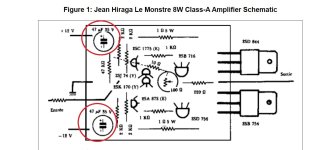
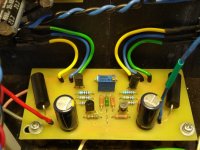
I started making the monster. There are a few things I'm stuck on. Why were 47uf capacitors installed, which are not in the diagram? What effect does it have?
Which of the 5watt resistors I have should I use? Thank you in advance for your valuable help.
I started making the monster. There are a few things I'm stuck on. Why were 47uf capacitors installed, which are not in the diagram? What effect does it have?
Which of the 5watt resistors I have should I use? Thank you in advance for your valuable help.
Attachments
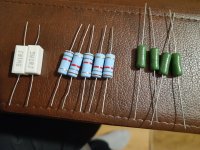
I wouldn't. Use Mills 5W, you will hear them.I would use ceramics on the left and I 've clamped them to the heatsink.
For as close a sound as possible to the original I'd highly recommend using AN Niobium 0.5W resistors for the input and feedback dividers.
Your input devices need to be curve trace matched + lowest possible Idss (if LS). If not you're dead in the water.
For local capacitance I'd say use a 0.1uF vishay 1837 MKP bypass and something like a 100 to 220uF lytic cap. Maybe Pana FR
Happy listening
Last edited:
To begin with the most important thing is that it works. Later you can try with better parts. For resistors you can freely use Dale RN60 and for power resistors Dale NS or MRA . Ohmite WN (pictured) is just as good as NS or MRA, but it is much cheaper.Hello,
I started making the monster. There are a few things I'm stuck on. Why were 47uf capacitors installed, which are not in the diagram? What effect does it have?
Which of the 5watt resistors I have should I use? Thank you in advance for your valuable help.
Attachments
Hello,I wouldn't. Use Mills 5W, you will hear them.
For as close a sound as possible to the original I'd highly recommend using AN Niobium 0.5W resistors for the input and feedback dividers.
Your input devices need to be curve trace matched + lowest possible Idss (if LS). If not you're dead in the water.
For local capacitance I'd say use a 0.1uF vishay 1837 MKP bypass and something like a 100 to 220uF lytic cap. Maybe Pana FR
Happy listening
Thank you for your help.
I used 2sk246 and 2sj103 for input. Idss 5.34mA and 5.28mA enough for these small jfets?
")
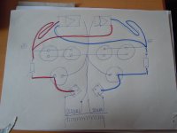
For maximum sound: resolution and homogeneity, in the case of Hiraga's Classe A, or Le Monstre - and also other half-wave amplifiers:
- Connect each half-wave amplifier to even just one secondary winding of the transformer - Two rectifier bridges or only two simple diodes required.
- With several parallel capacitors: route the voltage supply lines to the amplifiers in the opposite direction to the earth connection.
- Make sure that the cables to the amplifiers and power transistors are identical in length: per half wave and channel.
- Remove the thick copper bars and replace them with single wire, max. 1 mm diameter.
Attachments
Is the above designed to keep diode noise out of the amp circuit? Using a single diode per rail would need a pair of those metal cased items and a large amount of capacitance (maybe also a large inductor)
You could use 2 active rectifiers and join their outputs together at the centre of the caps /zero ref point.
You could use 2 active rectifiers and join their outputs together at the centre of the caps /zero ref point.
- Home
- Amplifiers
- Solid State
- Hiraga "Le Monstre"