Thanks tcpoint and TheGimp!
I checked your proposals but sorry to say they are poorly soldered which I will correct but functioning. I measured the otputs from the regs and reg 5 showed a short. After a while I found 2 shorts. The first one was some copper debris on the solder side under the ALPS potentiometer. The second one was my own doing... Pin 27 (DSD) and 28 3,3V was shorted. I tried it with HW settings so DSD was jumpered to GND so pin 5 of the reg 5 was grounded this way. Well, that reg was destroyed if not by the short then indeed by the quest of finding the short - it lost pin 5 in the process. It will now take about a week to get a new one... As a test - could I temporarily use one of the other 3,3V regs?
Brgds
I'm slowly getting mine built. So far I have all resistors, filters, MLC caps, V-regs, ref, small logic and am working on electrolytics.
I plan to add the connectors, then test the power supplies before adding the remaining ICs.
I'm still missing a couple of connectors and caps.
I plan to add the connectors, then test the power supplies before adding the remaining ICs.
I'm still missing a couple of connectors and caps.
What is nominal current draw when idle? Anyone measure it yet?
tks.
I went ahead and used the caps I had, substituting low esr 105C caps for the Silmic and Oscon caps. I'll order them and change them later after I've gotten used to this configuration to see how much difference they make.
Unit powers up and current draw levels off at 133mA when I hit 6.5V in.
Nothing smokes, LED 3 comes on (not real bright but certainly on). LEDS 1 & 2 are off unless I put my finger on the ICs to check for hot spots. Then LED 1 flickers.
Voltage regulators are all within spec.
Current draw at 7V in is 135mA.
Next I guess I need to get the IR receiver, Remote, and get the Arduino working.
The only test signal source I have is going to be the digital output of a computer CDrom drive till I get my ShigaClone working.
Hopefully I have a drive that I can use.
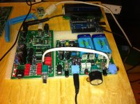
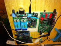
I'll post pictures later this evening.
tks.
I went ahead and used the caps I had, substituting low esr 105C caps for the Silmic and Oscon caps. I'll order them and change them later after I've gotten used to this configuration to see how much difference they make.
Unit powers up and current draw levels off at 133mA when I hit 6.5V in.
Nothing smokes, LED 3 comes on (not real bright but certainly on). LEDS 1 & 2 are off unless I put my finger on the ICs to check for hot spots. Then LED 1 flickers.
Voltage regulators are all within spec.
Current draw at 7V in is 135mA.
Next I guess I need to get the IR receiver, Remote, and get the Arduino working.
The only test signal source I have is going to be the digital output of a computer CDrom drive till I get my ShigaClone working.
Hopefully I have a drive that I can use.
I'll post pictures later this evening.
Last edited:
Hello,
is there anybody of you can tell me whether the WM8741 can swap it's digital filter settings during operation in hardware mode? I would like hear the difference between the settings but not shure it is works.
The oversampling function is also an issue for me.
Another question. The tri state "high impendance" position is how much sensitive? If I left it long enough does not it operates like an antenna collecting false signals. Maybe if the on the fly settings are OK then a 100nF ceramic cap + ferrite bead or whatever similar can solve the problem.
Hmmm, I got mine working sort of but only if I keep my finger on IC8 pin5 and the RST/UL pin which is for connecting the small boards... For now I will only use it for USB so I need to find what values theese pins should be set to for it to work (without the finger ") )
)
Brgds
)Brgds
Hmmm, I got mine working sort of but only if I keep my finger on IC8 pin5 and the RST/UL pin which is for connecting the small boards... For now I will only use it for USB so I need to find what values theese pins should be set to for it to work (without the finger
Brgds
Problem solved, I believe this is your flickering problem as well TheGimp...
http://www.diyaudio.com/forums/grou...dac-new-version-group-buy-11.html#post2959472
Brgds
Post the log file of errors.
Yes, I will have to revert to the original files first. The ones I am working with now ain't good anymore...
Brgds
I"m running Arduino 1.0 zip date 11/28/2011 7:33pm.
I think I have it up and running as I can talk to the Uno, and run a simple file for a test.
I've got the file "Arduino UNO Code.txt" dated 1/15/2012 7:05pm, is this what you are building with?
Since there is no revision number in the code it is difficult to tell for sure.
Turbon, when you post a file, please put a revision number in it and your name as editor so we can track the file and be sure we all are working on the same file.
Thanks.
Sven
OK, reverting to basics.
I run Aurdino 1.0 and compiled and loaded the following:
---
/*
Blink
Turns on an LED on for two seconds, then off for half a second, repeatedly.
This example code is in the public domain.
*/
void setup() {
// initialize the digital pin as an output.
// Pin 13 has an LED connected on most Arduino boards:
pinMode(13, OUTPUT);
}
void loop() {
digitalWrite(13, HIGH); // set the LED on
delay(2000); // wait for 2 seconds
digitalWrite(13, LOW); // set the LED off
delay(500); // wait for half a second
}
---
Works like charm.
Now load the LCD library as stated in the aurdino code from heartwinters email and try to compile the code - bang crash... Does not compile and there I am...
Brgds
You are doing better than me. I've got a parallel LCD/keyboard combo and tried to compile and download the "Hello World" sketch.
I can't get past
Binary sketch size: 2520 bytes (of a 32256 byte maximum)
avrdude: stk500_getsync(): not in sync: resp=0x00
I've got a serial LCD also but haven't found the spi driver yet.
I can't get past
Binary sketch size: 2520 bytes (of a 32256 byte maximum)
avrdude: stk500_getsync(): not in sync: resp=0x00
I've got a serial LCD also but haven't found the spi driver yet.
I got a question.
I really like the O2, but there is some modification I would like:
On the front of the amp, I would like the powerswitch to be, volume knob and one headphone output.
On the back of the amp, I would like the power connection, audio input and another headphone output(so when I'm gonna use the same headphone, I would rather connect it back than the front.
Like this; objective2 headphone amp - Hardware Canucks
Anyone done that before? I've tried to search and see if someone could make one for me, but without luck.
Hmmm, your question everlong should be asked in the O2 thread...
But anyway, the link you referred to shows the larger enclosure with the pcb somewhere near the top. The builder has then done some internal wiring to the new connectors at the bottom of the box. As I see it you better connect one pair of headphones at the time - otherwise they will interfere with the other in more than one way... But ask your question in the O2 thread - a lot of cunning people there.
Brgds
- Status
- This old topic is closed. If you want to reopen this topic, contact a moderator using the "Report Post" button.
- Home
- Source & Line
- Digital Source
- High Performance WM8741 Upsampling DAC New Version build thread (show 'n tell too)