Capacitor or resistor?
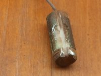
Well folks.. TONIGHT I will get these faulty components unsoldered and will try to cut them opened to "see" what's in the beast's guts..
What do you suggest? Dremeling longitudally or cross section?
Hi,
I agree looking at the pictures harder its a burnt out capacitor,
probably very similar to the other parallel capacitor shown.
If it measures resistance, it is very kaput.
rgds, sreten.
Well folks.. TONIGHT I will get these faulty components unsoldered and will try to cut them opened to "see" what's in the beast's guts..
What do you suggest? Dremeling longitudally or cross section?
I see better now. I thought maybe the yellow things were some sort of sticky foam or something for mounting, except I could not account for the extra wire.
Myself, I would use a razor blade or utility knife or xacto. I would just cut, poke, scrape, chip or try to peel up some layers. The dremel may sling around debris and goo and I don't think a full autopsy is actually needed in this case")
Also if it was a resistor you will most likely hit a ceramic core or something equally hard and kill the dremel blade quickly.
A capacitor should show up some layers fairly quickly. I would make a short cut lengthwise at one end.
Quite a flame job. Impressive.
Myself, I would use a razor blade or utility knife or xacto. I would just cut, poke, scrape, chip or try to peel up some layers. The dremel may sling around debris and goo and I don't think a full autopsy is actually needed in this case
Also if it was a resistor you will most likely hit a ceramic core or something equally hard and kill the dremel blade quickly.
A capacitor should show up some layers fairly quickly. I would make a short cut lengthwise at one end.
Quite a flame job. Impressive.
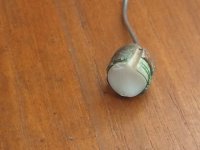
Autopsy of a..
Resistor!!!
I'll attach the pics here, but the toasted component is a wirewound resistor, with a ceramic core.
I dismantled the components from the board.. The "green" resistor wich is part of the treble circuit has a value of 18ohms.
The toasted components had a value of 15 and 17ohms. But can we trust what I measured? I mean, what was the original value when new?
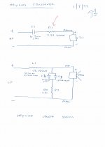
Other components, like I indicated in my small drawing are a 2uf+.91uf on the treble, and a 1uf on the bass circuit(with the resistor on top)
Hoping this help. So Steve, your circuit seems the most probable one.. he?
Resistor!!!
I'll attach the pics here, but the toasted component is a wirewound resistor, with a ceramic core.
I dismantled the components from the board.. The "green" resistor wich is part of the treble circuit has a value of 18ohms.
The toasted components had a value of 15 and 17ohms. But can we trust what I measured? I mean, what was the original value when new?
Other components, like I indicated in my small drawing are a 2uf+.91uf on the treble, and a 1uf on the bass circuit(with the resistor on top)
Hoping this help. So Steve, your circuit seems the most probable one.. he?
Attachments
Mystery solved?
Well.. how about the original value of the burnt resistor? it got so hot.. was the 15ohm (17 on the other) I read on my multimeter the value it had when new?
"All these things are LOST in time, like Tears in RAIN..."
Now get on with it. 15R 7W wirewound plus 1uF. I can't keep saying the same thing.
p.s. Minnesota Vikings on fire tonight! I'm having a good day.
mystery solved as to what the part was.
As far as being burned up, they still did have continuity, and only 1 wire layer so probably no shorted turns, so they may be fairly close to their original value.
And the 2 resistors are within standard 20% tolerance.
"15R 7W wirewound plus 1uF" - I agree. A perfect place to start.
As far as being burned up, they still did have continuity, and only 1 wire layer so probably no shorted turns, so they may be fairly close to their original value.
And the 2 resistors are within standard 20% tolerance.
"15R 7W wirewound plus 1uF" - I agree. A perfect place to start.
If they were using it to compensate for the Fs and slight rise of the driver, that resistor is best being about the value of Zmax at resonance for the driver. Usually, when I use that method the resistor is closer to 30-40 ohms, not 20 ohms, and it is usually a 15-20W model as well.
If you are keen on using a tank like system7 recommends, then a 15 ohm resistor is not the value I would employ. Typically a 4 ohm resistor is all that is necessary and won't decrease the effectiveness of the notch like the 15 ohmer might. Use a 4 ohm resistor if you use one in that position.
Technically speaking, the 4 ohm resistor is only there for the purpose of not shorting out the amp in the case of a second-order style xover, and can actually be totally omitted if you like.
Honestly what I would likely try is neither. I know this is kinda redesigning the system, but using an LC shunt as I explain herein will actually keep the 1st order method intact and kill what is likely above the xover that they tried to get rid of. I would try a 0.1uF cap and a 3.3-4.7uF cap in series across the woofer, and leave the coil as the only thing in series. This method will also not allow a rise in output above where the notch or tank were employed prior. The treble will not come from the woofer as well in the top-octave.
There's a few more things to try out,
Wolf
Hi foks,
I've resoldered the xovers tonight (finally got some time) according to system7 "tank notch 5khz" recommendation. They sound natural, but to my ears.. less lively. May be just an impression, since I have no way to measure them and see "before" vs "after". I will live with them as is for a little while and see if some other mods could be done.
Thanks for your help guys.
Too many projects going on..
Happy Holidays to come.
Hi folks,
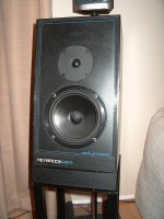
I have a pair of Heybrook HB2Rs that I've owned since 1988 (I bought new) and came across this thread while researching crossovers.
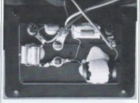
Like Sylvain, my crossovers were also damaged - in exactly the same way, in fact, with the resistor on the bass side burnt, although it still seemed to work. There doesn't seem to be any wiring fault as mine and the review photo's (see below) crossovers were wired up the same as Sylvain's.
On discovering the damage, since the drivers were still in excellent condition (I had them tested), I decided to get the crossovers replaced. This was a few years ago and the new crossovers were custom made by a shop/lab in Sydney (Australia) that design and test their own speakers. The result was mixed - slightly clearer top end and upper vocal range, but much reduced bass and overall a bit too "clinical" - and this was with the same amplifier (Amber Series 50b) and source (Cambridge Audio Azur 640C v2). Whilst I've listened to them plenty in the new configuration, I long for the overall "richness" of the original response and my thoughts turned to re-building the original crossovers.
I couldn't find the design anywhere, and even got in touch with Heybrook in the UK who, while being very helpful, couldn't locate the HB2R schematic. However, Heybrook did provide the HB2"C" (for "Classic") crossover spec and the Heylios spec (a later 2-way Heybrook design that, as far as anyone could recall at Heybrook, resembled the HB2R). Allegedly, the HB2R used the same drivers (Seas) as the HB2"C" but the HB2R had a radically revised crossover design. The story goes that the HB2 (or HB2"C" as it's now called) crossover was designed using the latest techniques at the time, but the speaker sounded dull and lifeless in reality. With the revised HB2R, Heybrook blindly experimented with crossover components until they found a combination that sounded great and didn't blow up (well, not immediately it seems), or at least that's what I heard.
Now that I've found this thread with its excellent information, I think I can piece together the original crossover design, or at least most of it.
And I might as well share everything else I have in case it's useful.
I've attached what I have:
(1) HB2"C" crossover schematic (as provided by Heybrook)
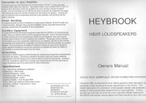
(2) HB2R Onwers Manual
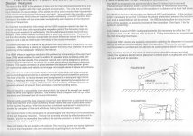
(3) HB2R Owners Manual, continued
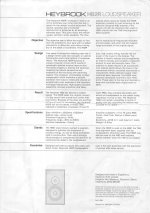
(4) HB2R Spec Sheet
(5) HB2R crossover photo (from original review in 1986)
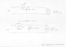
(6) Heylios crossover schematic (as provided by Heybrook)
(7) One of my HB2Rs (still looking good at 26 years old!)
(8) My attempt at reconstructing the HB2R schematic
For what it's worth, using the HB2"C" details as a guide, these would seem to be the "specs" of the drivers used in both the HB2"C" and HB2R:
HB2C/R Woofer
HB2C/R Tweeter
I did do some electronics theory a long time ago, but I'm afraid I'm far too rusty to rely on it, so I do have a couple of questions to put to the more expert members of diyAudio:
1. Going by the attached HB2R schematic, what do those circuits do, specifically (i.e. not just high-pass/low pass)?
2. If I rebuilt the crossovers as drawn (in my suggested schematic), would I be risking my drivers?
Thanks for reading. (BTW, If I go ahead with the crossover replacement, I might come back to ask an expert to verify my component choices before soldering, just in case).
I have a pair of Heybrook HB2Rs that I've owned since 1988 (I bought new) and came across this thread while researching crossovers.
Like Sylvain, my crossovers were also damaged - in exactly the same way, in fact, with the resistor on the bass side burnt, although it still seemed to work. There doesn't seem to be any wiring fault as mine and the review photo's (see below) crossovers were wired up the same as Sylvain's.
On discovering the damage, since the drivers were still in excellent condition (I had them tested), I decided to get the crossovers replaced. This was a few years ago and the new crossovers were custom made by a shop/lab in Sydney (Australia) that design and test their own speakers. The result was mixed - slightly clearer top end and upper vocal range, but much reduced bass and overall a bit too "clinical" - and this was with the same amplifier (Amber Series 50b) and source (Cambridge Audio Azur 640C v2). Whilst I've listened to them plenty in the new configuration, I long for the overall "richness" of the original response and my thoughts turned to re-building the original crossovers.
I couldn't find the design anywhere, and even got in touch with Heybrook in the UK who, while being very helpful, couldn't locate the HB2R schematic. However, Heybrook did provide the HB2"C" (for "Classic") crossover spec and the Heylios spec (a later 2-way Heybrook design that, as far as anyone could recall at Heybrook, resembled the HB2R). Allegedly, the HB2R used the same drivers (Seas) as the HB2"C" but the HB2R had a radically revised crossover design. The story goes that the HB2 (or HB2"C" as it's now called) crossover was designed using the latest techniques at the time, but the speaker sounded dull and lifeless in reality. With the revised HB2R, Heybrook blindly experimented with crossover components until they found a combination that sounded great and didn't blow up (well, not immediately it seems), or at least that's what I heard.
Now that I've found this thread with its excellent information, I think I can piece together the original crossover design, or at least most of it.
And I might as well share everything else I have in case it's useful.
I've attached what I have:
(1) HB2"C" crossover schematic (as provided by Heybrook)
(2) HB2R Onwers Manual
(3) HB2R Owners Manual, continued
(4) HB2R Spec Sheet
(5) HB2R crossover photo (from original review in 1986)
(6) Heylios crossover schematic (as provided by Heybrook)
(7) One of my HB2Rs (still looking good at 26 years old!)
(8) My attempt at reconstructing the HB2R schematic
For what it's worth, using the HB2"C" details as a guide, these would seem to be the "specs" of the drivers used in both the HB2"C" and HB2R:
HB2C/R Woofer
HB2C/R Tweeter
I did do some electronics theory a long time ago, but I'm afraid I'm far too rusty to rely on it, so I do have a couple of questions to put to the more expert members of diyAudio:
1. Going by the attached HB2R schematic, what do those circuits do, specifically (i.e. not just high-pass/low pass)?
2. If I rebuilt the crossovers as drawn (in my suggested schematic), would I be risking my drivers?
Thanks for reading. (BTW, If I go ahead with the crossover replacement, I might come back to ask an expert to verify my component choices before soldering, just in case).
Attachments
-
 My_HB2R_Speakers.jpg122.4 KB · Views: 249
 -
 Heylios_Schematic.jpg136.3 KB · Views: 154
 -
 HB2R_Xover_Original.jpg35.6 KB · Views: 168
 -
 HB2R_SpecSheet.JPG147.4 KB · Views: 165
 -
 HB2R_Manual2.JPG186 KB · Views: 219
 -
 HB2R_Manual1.JPG143.3 KB · Views: 230
 -
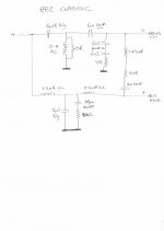 HB2C_Schematic.jpg39.2 KB · Views: 233
 -
 My_Suggested_Schematic.JPG51.3 KB · Views: 171
Heybrook HB2 R
Hey CobaltBlue,
I know it's been awhile since your last post re the HB2Rs.
Did you ever sort out replacement crossovers for your HB2Rs?
I read you had a replacement but weren't entirely happy with the end results.
In your post you've listed the drivers used but upon opening my boxes they've used both Seas drivers for tweeter and woofer.
Just curious as I've had my HB2Rs since '87 and can't let them go.
cheers
Hey bauerpower, CobaltBlue
If this still may have any value for you:
The shematic of HB2R „reconstructed” crossover on the CobaltBlue's last drawing is evidently fault - the 15 ohm R2 resistor must be placed parallel to L1 & C3, not across the woofer – and i'm sure this is the reason of the „much reduced bass and too clinical sound” altough its not risky for the bass driver in any way.
BTW the symbols of drivers are of HB2's. HB2R have not audax but seas transducers.
Regards,
Jacek.
- Status
- This old topic is closed. If you want to reopen this topic, contact a moderator using the "Report Post" button.
- Home
- Loudspeakers
- Multi-Way
- Heybrook HB2R someone?