I think mainly with guitar amps the difference, if you ignore the possible increase in voltages, is sag.
In a lot of the vintage guitar amps with tube rectifiers the low filtering can't keep up with the amp when playing loud so you will get a voltage sag when the current demand exceeds the supply.
This causes a kind of compression that a lot of blues players love.
For more modern tones a SS rectifier is generally the better choice because you can use bigger filter caps which makes the amp more responsive and faster feeling.
But I have heard stories where somebody didn't do any research and just plugged one of the SS modules in and then the amp commenced to blow up because of higher voltages that affect tubes and caps.
With audio amps I think a tube rectifier to my ears seems a bit warmer, more dynamic than SS.
It's just a matter of taste which is subjective.
For tube purists, most don't want any Silicon in their amps.
I would be interested to know a part number of a schottky diode with a 1KV PIV rating as this might be useful..
CREE Semiconductor Corp SiC Schottky C2D05120A 1200 volt 10A $8 each at Digikey.
I have not tried them. I have tested CREE SiC RF power fets in my day time engineering job. Great parts but far outside our price range. We are now working with GaN for broadband RF power in the 10 MHz to 4 GHz range. GaN fets will be making inroads into consumer SMPS and possibly linear applications in the near future. Very fast, very low gate capacitance and high voltage capability.
Hey Structo, I love your avatar. When I was six years old I heard a blood curdling scream from the basement. By the time I got downstairs my older sister was laughing maniacally. When she finally calmed a bit she handed me a straightened out diaper pin and said,"stick this in there." And I , at my sister's command, stuck the pin in the electrical outlet. My muscles contracted so hard I was lifted off the ground and flung across the room into the opposite wall. At this my sister began to laugh so hard that she couldn't breathe. And after a few seconds I began to laugh as well. We were a sick family.
Many years ago (when I was a mere stripling) I bodged an EL84 amplifier.
Speaking of explaining, what does 'bodged' mean?
Hey all,
I'm planning to build a pair of Dynaco Mark IV clones. Would the 5U4GB tube substitute for the GZ34? I will be using a pair of 250MA 800 volt power transformers (Triode's Mark IV PT is rated at only 150MA) Would this combination give me a stronger power supply? And would there be a downside?
I'm planning to build a pair of Dynaco Mark IV clones. Would the 5U4GB tube substitute for the GZ34? I will be using a pair of 250MA 800 volt power transformers (Triode's Mark IV PT is rated at only 150MA) Would this combination give me a stronger power supply? And would there be a downside?
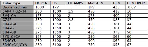
Just as with other tubes, rectifiers have their own set of specifications.
Some drop more voltage, some take more current to operate, some have different first capacitor maximums.
As you can see the GZ34 only drops 10v where as the 5U4GB drops 50.
Plus the 5U4GB draws another amp of current on the heater.
Some drop more voltage, some take more current to operate, some have different first capacitor maximums.
As you can see the GZ34 only drops 10v where as the 5U4GB drops 50.
Plus the 5U4GB draws another amp of current on the heater.
Last edited:
Structo,
That might not be a bad thing. My transformers are 800 volts, and the Mark IV is 740. So the 50 volt drop will help. The question would be is the heater supply strong enough? But your table answers that question too. As the Amps they came out of had two 5Y3gt's in parallel.
That might not be a bad thing. My transformers are 800 volts, and the Mark IV is 740. So the 50 volt drop will help. The question would be is the heater supply strong enough? But your table answers that question too. As the Amps they came out of had two 5Y3gt's in parallel.
I believe those little ones are just a couple of silicon diodes. The copper ones are supposed to have some series resistance added so that they don't result in a lot of extra B+ and probably an inrush limiter. I've never taken one apart, but that is the impression that I got.
Weber Copper Caps are great for reforming capacitors. They begin to conduct at low voltages, unlike their glass predecessors.
You can learn a lot about them with your voltmeter. Watch the B+ rise and the rate of the rise, vs. using a tube rectifier. That will help you to understand (viscerally) their best application.
You can learn a lot about them with your voltmeter. Watch the B+ rise and the rate of the rise, vs. using a tube rectifier. That will help you to understand (viscerally) their best application.
Hello,
For my Mark IV clones I'm debating using the original GZ34 or the larger 5U4GB. Both use octal sockets and their pinouts are identical. Looking at the above table as far as I can see. If the power transformer is capable there is no reason this would not work. The transformers originally powered two 5Y3's which are almost exactly the specs of one 5U4GB. Would this result in less 'sag' as it is described above?
For my Mark IV clones I'm debating using the original GZ34 or the larger 5U4GB. Both use octal sockets and their pinouts are identical. Looking at the above table as far as I can see. If the power transformer is capable there is no reason this would not work. The transformers originally powered two 5Y3's which are almost exactly the specs of one 5U4GB. Would this result in less 'sag' as it is described above?
Far back, in the distant mists of time, bodgers were travelling people who made a living by constructing chairs out of the dead timber available in the woods. Hence bodging means making something out of available materials without spending any money. It also implies poor workmanship, something badly put together, which I'm sure EC8010's effort wasn't.Speaking of explaining, what does 'bodged' mean?
Way back in this thread some years ago, Sy said:
So how do you know if there are components that require a slow warmup time?
Specifically, I've got an Eico HF-87 with the usual CRC(RC) type of power supply. When the amp is powered up, there's 400+ volts on the B+ supply, and since there's little current draw downstream, the end of the CRC chain has about 400 volts on it and the 12AX7 (and the 6SN7's) have that same 400V on the plate. The 12AX7 datasheet says the max plate voltage is 300V, so it looks like it's well above the rated voltage at startup. On the other hand, I can't remember it losing a 12AX7, so there probably isn't a practical problem. All the caps in the supply chain are rated at 450V, so they should be OK.
Is it fair to assume that since the amp has been running this way for years without problems that there isn't anything to worry about? I'd figure that pretty much all the amps with silicon rectifiers and unregulated supplies are running this way.
Jim
Assuming it's just some silicon rectifiers in a copper package, it will do all that's claimed. But... you have to be careful that there are no components in the amp which require a slow warmup time..
So how do you know if there are components that require a slow warmup time?
Specifically, I've got an Eico HF-87 with the usual CRC(RC) type of power supply. When the amp is powered up, there's 400+ volts on the B+ supply, and since there's little current draw downstream, the end of the CRC chain has about 400 volts on it and the 12AX7 (and the 6SN7's) have that same 400V on the plate. The 12AX7 datasheet says the max plate voltage is 300V, so it looks like it's well above the rated voltage at startup. On the other hand, I can't remember it losing a 12AX7, so there probably isn't a practical problem. All the caps in the supply chain are rated at 450V, so they should be OK.
Is it fair to assume that since the amp has been running this way for years without problems that there isn't anything to worry about? I'd figure that pretty much all the amps with silicon rectifiers and unregulated supplies are running this way.
Jim
- Status
- This old topic is closed. If you want to reopen this topic, contact a moderator using the "Report Post" button.
- Home
- Amplifiers
- Tubes / Valves
- Heresy? Replacing tube rectifier w/Weber Copper Cap