acid_k2 said:Inverting input is not a problem.
Output voltage is adjusted by R4, so I have to adjust it for half single-rail voltage with inputs grounded..... or maybe I'm wrong
Almost. Drift would be a problem, resulting in some sort of offset most of the time. This would be an easy fix with a DC servo. But by the time you do that, it would be cheaper and easier to just add the diff pair stages to both halves. Four miserable cheapo PNPs and a handful or resistors and caps...
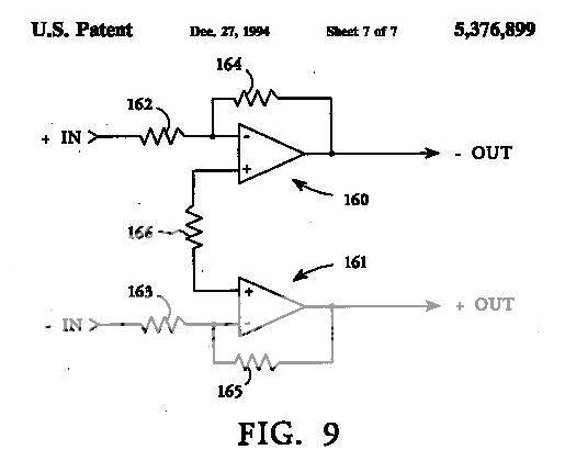
Bridged, with bias and off-set controls. Anti-saturation diodes added too.
An externally hosted image should be here but it was not working when we last tested it.
PB2 said:
Almost same schema.
PB2 said:
Sorry should have been Dec. 1967, not 1969.
djk said:Bridged, with bias and off-set controls. Anti-saturation diodes added too.
An externally hosted image should be here but it was not working when we last tested it.
You're using a negative supply. Cheater!
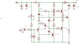
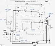
Here's my variant, with an additional PNP input transistor (topology derived from JLH).
Q1 can be just about any small signal PNP, like BC558/559/560 etc. The VAS transistor is fairly critical - selected BC550c with beta > 500 should be ok, but I prefer the 2sc3112 with hand-selected beta > 1500. Q3/Q4 can be just about any power-darlington pair - choices include Sanken 2SB1620/2SD2488 (hard to find, but about the best), TIP142/147, BDX33C/34C, 2N6052/6059 (rugged and sonically open). D1,D2, D3, D4 are 1N4148.
For higher power, it's possible to increase the supply voltage to about 50V, with appropriate changes to R2, R3, VR1, R7, R9 to set the output bias point to about half the supply voltage. Gain is set by (1+R6/R8). Maximum slew rate is set by the VAS current divided by Cdom - here, it's 5 mA / 47 pF ~= 100V / usec (in practice, it will be lower because of the O/P stage base(s) loading the VAS bootstrap source).
Edit: Added schematic.
Attachments
linuxguru said:Probably worth increasing the bootstrap cap to 100-220 uF, 50v - should improve the bass response below 30 Hz. Also a small bypass cap - say 1-22 uF, around the diode/resistor Vbe bias chain should improve the highs.
A small miller capacitance of around 33-100pF between the base and collector of Q1 should help suppress AC instability.
I've built something similar to this, but with a Vbe multiplier for crossover biasing, bias stabilization resistors of 0.2R in the emitters of Q2 & Q3, and 2N6054/59 TO-3 output darlingtons.
Hi
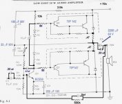
I did some mod to the Fairchild amp for more power, is it ok ?
Where can I place a phase lead capacitor in that circuit ?
Thanx
Cheer
Paul
Attachments
gee, add a diff amp before Q1,and run it off a split supply, and you basically have the same amp denon, yamaha, and pioneer use in their recent surround receivers. i think harmon kardon does that too, using darlingtons for the output devices, eliminating separate driver transistors.
Sony does that too, with Sanken Darlington outputs and a proprietary analog IC input stage which has everything except the Vbe multiplier, which is a discrete Sziklai.
I'd second the recommendation of either an LTP or single PNP before the VAS - it provides a significant amount of open-loop gain which can be traded off for lower distortion.
Apart from that, the mods look benign, but I'd advise simulating them to see what their impact is.
I'd second the recommendation of either an LTP or single PNP before the VAS - it provides a significant amount of open-loop gain which can be traded off for lower distortion.
Apart from that, the mods look benign, but I'd advise simulating them to see what their impact is.
- Status
- This old topic is closed. If you want to reopen this topic, contact a moderator using the "Report Post" button.
- Home
- Amplifiers
- Solid State
- Here's a 20 watt amp, very simple but sound good