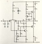
unclejed613 said:i hope that 47uf compensation cap on Q1 is a typo....
Hi
Yes it was a typo error, I did post a corrected schematic in a second post, with a 47 pf cap.
Btw, I would like to try this amp circuit but do 70v supply are ok for TIP142 and TIP147 ?
They have a Vceo of 100v.
I do not have a simulation software, anyone can do a simulation on my circuit ? .
Thanx
Cheer
Paul
Paul, since you increased the supply voltage and changed the values of the bootstrap resistors the DC offset control no longer works in the proper range and the circuit operates with a huge misbalance in the DC levels. With the trimmer set to about middle of the dial the DC voltage at the point between the emitter resistors (of the ouput devices) is about 20V while it should be 35V! Even when the trimmer is turned to its fullest resistance you can bias that point only to about 25VDC. That is is still 10 volts off so the trimmer resistance must be higher. Replacing the trimmer with a 500 kilo-ohm one should to get to the ballpark of things.
Increase in rail voltage also increases headroom because the closed loop gain remains unchanged, thus input sensitivity changes. The new one is approximately two volts, which seems quite high. That's of course just a minor issue.
Increase in rail voltage also increases headroom because the closed loop gain remains unchanged, thus input sensitivity changes. The new one is approximately two volts, which seems quite high. That's of course just a minor issue.
general rule of thumb for Vceo of output devices is about twice the total rail voltage ( in this case, 140V between the rails, so your Vceo should be 300V). many 100W designs (with 65 to 70V rails) use 200V or 250V (instead of 300V) devices very successfully, so it's not a hard and fast rule. 100V devices might be pushing the envelope, as you will have a very limited Safe Operating Area.
Hi
After a look in my parts bin I see that I don't have 47pf capacitor. I have a lot of 15pf capacitors.
For the 47pf compensation cap on Q1 (or on a vas transistor of any amps), is it do any sonic differences to put few 15pf capacitors in parallel for a compensation cap ?
Thanx
Cheer
Paul
After a look in my parts bin I see that I don't have 47pf capacitor. I have a lot of 15pf capacitors.
For the 47pf compensation cap on Q1 (or on a vas transistor of any amps), is it do any sonic differences to put few 15pf capacitors in parallel for a compensation cap ?
Thanx
Cheer
Paul
Oh, come on!!
This is a *very* simple power amp, which is interesting because of simplicity itself.
The fact that it works reasonably well is an added bonus.
Trying to complicate it, bridge it, quadruple its power, etc, is *ridiculous*.
You want a better/louder/more powerful amp?
OK, get a proper schematic (there are millions) and build it.
You want a Harley Davidson?
Ok, go get one (or buy a good Japanese motorcycle for 1/5 the price), don't waste time and money "tuning" a pizza delivery bike.
Just sayin'
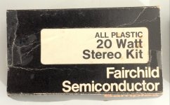
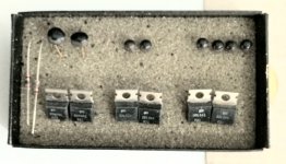
This is about the Fairchild All Plastic 20 Watt Stereo Kit. I just got one that has never been used, and there is no Darlington transistors, tested them to make sure, and the numbers on outputs are strange. Has Samples on side of box. I designed a better one in the 70s that had no bootstrap and put out 30 watts on same voltage. There were Darlington transistors in the 70s, came in TO-5 and TO-18 cases with 4 leads.
Attachments
Hi fooeywuffle,
Oh my! That amplifier doesn't like low impedance loads at all! Ever hear of keeping it simple? Right here we are looking at too simple. Did ja build it?
Those are "house numbers" that we all knew and loved. The dark days of everything was a secret. At least they did one thing well. They made certain that the tail current was stable and not too affected by voltage variations.
Cool find!
-Chris
I figure 16 ohm would be OK. The one I designed had driver transistors, so would work on 8 ohm. 4 ohm wasn't around much in those days. No, I didn't make one. Since it is probably a collectors item, want to leave it complete. I have thousands of transistors I can use to make one. But like you say, not really a good design. Still working on a Germanium 35 watt a channel amp, and might actually finish it some day. I did finally finish the ribbon tweeters. What a labor intensive project that was!
Ray
____________________________________________________
If brute force doesn't work, you aren't using enough of it!
Ray
____________________________________________________
If brute force doesn't work, you aren't using enough of it!
Hi Ray,
Yeah, I have to agree with you. The kit is a collector's item for sure.
You made a pair of ribbon tweeters? I am impressed. That was work.
Hey, I like your choice in dogs! I have two standards and a miniature. Once you have had a poodle, not much else comes close in my view. Does yours burp too?
-Chris
Hi stocktrader200,
Nope. Those parts suffer from beta droop big time.
Sorry but the distortion would be very high still, and you haven't accounted for peak currents and reactive loads. The amplifier is a nasty little thing, but it does illustrate the uses of their parts. It might have sounded "okay" on the poor speakers of that time era, but not today!
-Chris
Yes, I'm sure somebody would like one complete and un-used. Not really good for actual use.
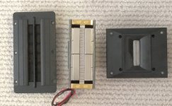
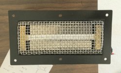
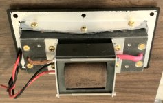
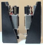
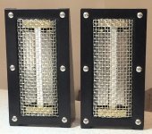
Those ribbon tweeters are a lot of metal work including the very low impedance to 8 ohm transformers. I made 4 of them, but have to make 2 more transformers. They are at least twice as loud as any tweeters I have bought. And a lot clearer sound. The ribbon is 4 inches, iron part 5 1/4 inches, and bezel 6 1/2 inches.
I actually have no pets. Not my thing. Parents ruined that for me. The avatar is for Quiche_Le_Poodle on eBay.
I agree on the beta problem. I used to build amps using 30 amp outputs for 35 watts because of the low beta of most Silicon transistors and the droop problem. Finding any with gain of over 50 at a good current is rare. Germanium ones do, but they suffer from low Ft. There are some Japanese ones with a gain of 300, but would have to parallel around 10 of them to get 5 amps. The smaller ones, there are Japanese ones with a gain of around 3000, not darlington, but I have never tried them.
Ray
____________________________________________________
If brute force doesn't work, you aren't using enough of it!
Attachments
Hi Ray,
Wow, those are good looking tweeters! Nice job!
Sorry to hear about the pet situation. I find they add a lot to life, even if they mostly sleep. Poodles don't shed very much, and their coat is hair as opposed to fur. They don't cause allergic reactions in people. Cats, sure, but not people!")
-Chris
Wow, those are good looking tweeters! Nice job!
Sorry to hear about the pet situation. I find they add a lot to life, even if they mostly sleep. Poodles don't shed very much, and their coat is hair as opposed to fur. They don't cause allergic reactions in people. Cats, sure, but not people!
-Chris
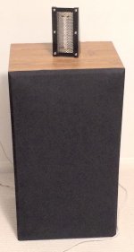
Thanks. I put the first 2 as add-on for TV, and for now, classical music. I hear notes I never did before. AR speaker not that great.
Doesn't matter about pets, I have no use for them, or a wife. I prefer to live alone without all the mess and hassle.
______________________________
If at first you don't succeed, get a bigger hammer!
Doesn't matter about pets, I have no use for them, or a wife. I prefer to live alone without all the mess and hassle.
______________________________
If at first you don't succeed, get a bigger hammer!
Attachments
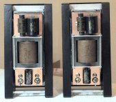
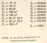
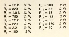
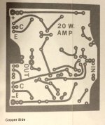
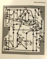
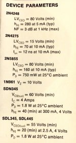
More photo's of the Fairchild 20 watt amp.
_______________________________________
If at first you don't succeed, get a bigger hammer!
fooeywuffle,
Thank you!
Regards,
Albert
- Status
- This old topic is closed. If you want to reopen this topic, contact a moderator using the "Report Post" button.
- Home
- Amplifiers
- Solid State
- Here's a 20 watt amp, very simple but sound good