I'm thinking this transistor is some kind of feedback to regulate the output supply. It has a 100 ohm 2 watt resistor from the output of the supply to drain of Q613. Source is tied to ground. The gate then goes somewhere but I dont know where.
I removed Q613 power supply stayed on a little longer but then fried. oops.
oops.
Once Q613 was removed U4 also got hot!! and r21 desolodered itself. Not sure how U4 comes into the equation, its a 555 timer to something.
Removed the supply transistor and R21 and amp turn back on and the gate of supply transistors stays switching.
So now I need to order more parts from digikey. I might have to give up on this amp before it sinks me in a hole.
have you had any luck with Vishay transistors?
I'm thinking of buying these because I would like to also replace the rectifier and digikey doesn't carry it. http://www.mouser.com/Search/ProductDetail.aspx?qs=/RKvNCQzLu0R%2bpFoqVUQ5w==
I removed Q613 power supply stayed on a little longer but then fried.
oops.Once Q613 was removed U4 also got hot!! and r21 desolodered itself. Not sure how U4 comes into the equation, its a 555 timer to something.
Removed the supply transistor and R21 and amp turn back on and the gate of supply transistors stays switching.
So now I need to order more parts from digikey. I might have to give up on this amp before it sinks me in a hole.
have you had any luck with Vishay transistors?
I'm thinking of buying these because I would like to also replace the rectifier and digikey doesn't carry it. http://www.mouser.com/Search/ProductDetail.aspx?qs=/RKvNCQzLu0R%2bpFoqVUQ5w==
R21 feeds the 555 timer which drives the small transformer near it. It drives it through C7.
It's possible that there was a problem with the 555 or the transformer and when the transistor was removed, the protection circuit could no longer shut down the amp.
If I'm not mistaken, this tiny supply powers the U1, 2 and 3. They are used for signal sensing to power up the amp. If any of these op-amps were shorted, it could have caused excessive current flow in this circuit.
When the square yellow transformer is operating, U1-3 get power from it (via the diodes next to R25). When that supply switches off, the 555 switches on and those ICs get their power from the tiny transformer. The voltage is significantly lower than ±15v. There is a 15-20 second turn-off delay for the square transformer.
If I'm not mistaken, there was a diffference between rev3 and 10 with regards to the operation of the 555. In the later revision, the 555 didn't receive power unless signal sense was selected. In the rev3, the 555 oscillated no matter the setting of the signal sense switch.
I don't think you'll find any voltage on the tiny transformer with the 555 out of the circuit.
I haven't had any trouble working on them without the sink.
When troubleshooting, I don't generally have the amp 'on' for long periods of time. I'll turn it on long enough to check the voltage at key points, power it down, follow the circuit a bit farther, power it up and check the voltage at the next point.
If there is a problem that's taking a long time to troubleshoot and the amp has to be powered up during the entire process, I'll pull the outputs or watch their temperature very closely.
As long as you monitor the temperature of the power transistors that are normally on the sink, you shouldn't have any problems.
How many parts failed?
Have you determined the function of Q613?
All the supply transistors died. I'm still not sure what purpose that transistor has. Its an irf540 and has a 100 ohm 2 watt resistor going from the output of the supply directly to the drain of q613. The Source is tied directly to ground.
On start up there is 13V tied to the gate. So I haven't figured out what purpose it serves yet. My guess is its some kind start up circuit. Maybe ties one of the inductor coils low until a start up check is done then release it once start up check has passed. That's my only guess.
If its just a start up circuit I dont know why it would have caused the transistors to die. There would need to be a serious short somewhere to kill all 8 Transistors that way, as well as being current limited to 3amps. After they shorted they could sink the entire 3 amps without getting warm to the touch. So that made me think its some kind of feedback to limit the output voltage and maybe that went high enough to fry the transistors. But that doesn't make much sense either, and I dont see any other connection that could possibly be used as feedback unless its an internal layer.
It sounds like it's part of a shunt regulator. It could be a drain for the rail caps (like MTX used in some of their amps) but removing it from the circuit shouldn't have caused the damage you found.
With the damage you described, I would have expected it to be a regulator for the 12v feeding the gate drivers in the PS and the 555 via R21 but a 100 ohm, 2w resistor can't drop 60+v.
It wouldn't have required any significant current to kill the PS FETs if the drive voltage went above 20v. Are the tabs of Q609 and Q610 tied directly to B+?
Posting pic of Q613 its the irf44z transistor sitting between the filter and the transformer. You can see the resistor sits between these as well. That resistor connects to the + terminal of the rectifier and the drain of the transistor. The source is tied to ground.
An externally hosted image should be here but it was not working when we last tested it.
Again, I think it's only purpose is to drain the rail caps. Under normal operating conditions, from a cold start there is no voltage (80v rail). When the amp starts, the control/servo circuits receive power THEN the main rail voltage is generated. It's possible that the amp makes a loud pop or has other difficulties if cycled on-off-on very quickly. Q613 could be used to make sure the rail caps are drained before the amp starts. Of course, this is only a guess.
It appeared that pulling Q613 caused the amp to fail. Is it possible that something else caused the failure?
Does the amp still shut off with no Z44s in it?
It appeared that pulling Q613 caused the amp to fail. Is it possible that something else caused the failure?
Does the amp still shut off with no Z44s in it?
No the PWM stays on. Amp never really shut off before just the power supply would cycle on and off. The green light stayed lit the entire time. Something would pull the compensation and soft start pins low causing the supply to cycle.
I dont know what else would have caused the failure because nothing else was different.
I dont know what else would have caused the failure because nothing else was different.
So I traced it up to d400 and the transistor it connects to. This looks like what supplies the power to the PWM. When the amp tries to turn on the voltage dips and d400 does not recover immediately this drops to 0 and gets stuck there. It also looks like the transistors supplying the Z44s are shot. Does anyone know the part numbers for these?
You're correct Q400 drives pin 8 of the 10 pin connector which goes to pin 13 of the PWM driver board. This transistor is controlled by pin 1 of U400. The amp is probably shutting down due to a fault and the protection circuit is sending a shutdown signal to U400.
D400 is a reverse protection clamp to protect Q400. The voltage on the collector of Q400 isn't switching back on because it's not being driven on by pin 1 of U400. It's probably a delay built into the protection circuit.
The following are the voltages I read on U400 in a working amp. Pins 1-14 top to bottom. Hopefully, only one pin has an error and you can track it from there.
0.972
5.73
1.388
13.47
5.80
5.05
12.20
12.29
5.63
9.79
0.000
1.406
5.24
0.969
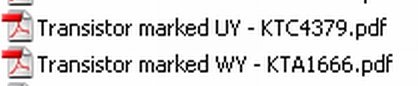
The attached photo are the original part numbers. I've been using 2SB1260s for the PNPs because the originals are difficult to find. I've never seen one of the NPN drivers fail.
D400 is a reverse protection clamp to protect Q400. The voltage on the collector of Q400 isn't switching back on because it's not being driven on by pin 1 of U400. It's probably a delay built into the protection circuit.
The following are the voltages I read on U400 in a working amp. Pins 1-14 top to bottom. Hopefully, only one pin has an error and you can track it from there.
0.972
5.73
1.388
13.47
5.80
5.05
12.20
12.29
5.63
9.79
0.000
1.406
5.24
0.969
The attached photo are the original part numbers. I've been using 2SB1260s for the PNPs because the originals are difficult to find. I've never seen one of the NPN drivers fail.
Attachments
- Status
- This old topic is closed. If you want to reopen this topic, contact a moderator using the "Report Post" button.
- Home
- General Interest
- Car Audio
- Help with JL 500/1 2nd one