Maybe Anatolij (Wavebourn) is on holiday - I am surprised he has not appeared, and explained (and defended) his circuit.
It's pretty neat, actually. I hope he won't mind if I try to explain.
Thank you Rod!
")
It seems to me you were born to teach students.
You don't have to bypass the resistor with a cap. You assume maximum gain is needed from the stage, which isn't usually the case. Otherwise, I pretty much agree with the points you made.
We don't have to bypass resistors by caps; we don't have to eliminate caps in cathodes; and we don't have to use tubes at all. Unless we are trying to achieve some unbelievably crystal clear sound reproduction. Preserving smoothness of transfer curves, every drop of power amplification, bit by bit, we are getting excellent results.
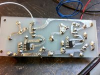
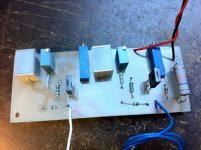
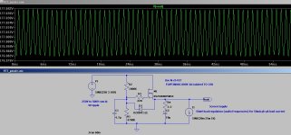
Today I etched two PCBs and got both gyrators working fine with a breadboarded driver. Tried a single 6J5 and then an 6SN7 with both triodes paralleled.
Also made my first SMD soldering experience and got those BSP225 in the board!
Things went pear shaped when I replaced my existing CCS board in my 45 SE amplifier with either boards. Again, got my HT supply regulator oscillating. This was what I really needed to throw away the feedback regulator - previously I posted for some help on this and managed to stabilise it with a couple of capacitors in the HT rail.
Back to the workshop, now to redo the HT supply
Cheers,
Ale
Attachments
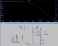
Version 1 attached is the current one. I take is nearly impossible to simulate the complete system end to end frequency response. The raw supply is a 5Z4P hybrid rectifier with a CLC stage. I have added the two CCS (6J5 drivers) which drag a total of 14mA and the two 45 output valves (34mA each).
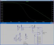
Version 2 is a simpler zener regulator which I tempted to try now.
Otherwise I need to buy a 2K 25W clamp resistor and forget about the bloody regulators .
.
Reason why I have such a high raw supply is because I have a power transformer which if I don't use a hybrid rectifier the output voltage is around 330V which is low for what I need at the driver stage. Therefore I ended with teh 550V.
Any help is highly appreciated....
Cheers,
Ale
Version 2 is a simpler zener regulator which I tempted to try now.
Otherwise I need to buy a 2K 25W clamp resistor and forget about the bloody regulators
.Reason why I have such a high raw supply is because I have a power transformer which if I don't use a hybrid rectifier the output voltage is around 330V which is low for what I need at the driver stage. Therefore I ended with teh 550V.
Any help is highly appreciated....
Cheers,
Ale
Attachments
What HT regulator are you using?
Any idea?
I will go and build the alternative regulator this weekend. Also bought some wire wound resistors to get rid of it in case it doesn't work
Cheers,
Ale
Hi Ale, to think about what's happening, consider Q1 base. This will be pinned 0,6V above the zener stack (which is not moving far) - in turn preventing the R3-R4 network from floating up to the expected level.
Such a condition will mean that the feedback network current will vary wildly will B+ voltage, which will not help with oscillation.
Iko is right, it's very tough to design a HV regulator that will not stamp on the sweetness of the 45SE.
Even when we have the dynamics right, we are left with the fact that series regulators cannot very well deal with SE endstages - since transformers an speakers present an inductive load to the supply. The series regulator reacts badly to a reverse flow of charge (from a sudden reduction in demanded current). All it can do is turn-OFF, when what's required is to divert the reverse current to GND.
To do this right requires a shunt regulator - my current lab project, in fact.
In the meantime, I would recommend using the zener stack directly on the FET gate (ie, a passive regulator) if you don't want to run unregulated. Some idle current (bleed resistors) might help with the sound, an area well worth experimentation time.
Thanks Rod for the input! This is a constant learning experience which I'm enjoying a lot!
Is it not the passive regulator you're suggesting the second circuit shown on the right in my previous post?
How will you add a slow start? Will a current source replacing the 33K resistor do the job?
Thanks
Ale
Is it not the passive regulator you're suggesting the second circuit shown on the right in my previous post?
How will you add a slow start? Will a current source replacing the 33K resistor do the job?
Thanks
Ale
Thanks Rod for the input! This is a constant learning experience which I'm enjoying a lot!
Is it not the passive regulator you're suggesting the second circuit shown on the right in my previous post?
How will you add a slow start? Will a current source replacing the 33K resistor do the job?
Thanks
Ale
Ale, You could use your circuit Nr.2 for a passive regulator, yes.
If you would prefer a soft start, try something like the attached. It shows a 4,7uF film capacitor in the gate circuit (4,7u/630v MKT is very low cost at Rapid).
You can also use an electrolytic, but these leak high currents, so the resistor must be much lower.
This circuit is unregulated, but I don't think it is very important for a well-designed SE stage. The passive FET circuit does give good 100Hz rejection, and in fact good noise rejection up to quite high frequencies - this is VERY important!
Attachments
R-C network between the zener stack, and the FET gate.
This provides filtering of noise, including zener noise (this is necessary, for sure), and the RC also provides a slow rising ramp to the output. Try some values in LT spice, or just keep in mind that their time-constant is R * C (seconds), so 4,7u/2,2M has around 10 seconds of tc.
This provides filtering of noise, including zener noise (this is necessary, for sure), and the RC also provides a slow rising ramp to the output. Try some values in LT spice, or just keep in mind that their time-constant is R * C (seconds), so 4,7u/2,2M has around 10 seconds of tc.
O, the output network.
This is something to use or ignore, according to taste.
If the R is present, the capacitor will interfere less with the transient response of the regulator. With no resistor, the C will dominate the response, at least at low frequencies.
So, depending on the quality of the output cap, you can adjust how much it contributes to the transient behaviour of the whole.
In a less hand-waving view, (and this applies much more to feedback regulators than this passive reg), the RC network can be optimised for values by applying step-changes in load-current, and looking at the voltage output's response.
Play in LTspice, too, and check transient responses that way!
Either way, this is a low-cost route to tweeking the sound to your taste.
Regulating the driver makes some sense. A shunt regulator for the output stage... that's a lot of heat that you'll need to dissipate. The shunt device will pass continuously some current, like a class A amp. But if you feel brave, here's a shunt regulator that I've been using, and it has very good performance.
http://www.diyaudio.com/forums/power-supplies/197332-hv-shunt-regulator.html
http://www.diyaudio.com/forums/power-supplies/197332-hv-shunt-regulator.html
Which devices do you use for currents around 5 mA?
Anatoliy,
Would you please take the time to explain what happens below 5mA standing current and why the P-type circuit is superior at low currents?
Thanks!
Anatoliy,
Would you please take the time to explain what happens below 5mA standing current and why the P-type circuit is superior at low currents?
!
Michael; I explained already: P-type devices are not superior in general. P-type devices that I have in my garage are superior to N type devices I have, in terms of capacitances. That's why I asked the question about "which devices do you use", read "which devices should I buy the next time"
Michael; I explained already: P-type devices are not superior in general. P-type devices that I have in my garage are superior to N type devices I have, in terms of capacitances. That's why I asked the question about "which devices do you use", read "which devices should I buy the next time"
Thanks! I wasn't sure what you were getting at...
So the FQP1N60 devices I have with 3 pF typical Crss are pretty good, DN2540 are typical 1pF, and down below 1mA I may use the LND150 with a typical Crss of 0.5 pF. (all provided there is Vds of about 20V or more).
1mA of signal current and 5pF capacitive load results in a slew rate limit of 200V/uS.
- Status
- This old topic is closed. If you want to reopen this topic, contact a moderator using the "Report Post" button.
- Home
- Amplifiers
- Tubes / Valves
- Help with gyrator