Got it!
What exactly is the reason you chose to eliminate the LPT current sink?
This being a low power amplifier?
For me, coming from tube circuits, it is a little bit difficult to understand how you choose the VAS quiescent current, and what implications it has. With tubes, you just find the output voltage swing you need for the required output power, and you desing the previous stages to achive the voltage swing required by the output tubes (of course, there's more, but this is the idea).
With SS amplifiers, I know that gain is the product of the transconductance of the LPT, times the current gain of the VAS, times its load impedance. We have an active load, so this last guy should be high. How can I find a good starting point for the VAS bias?
One for tomorrow ")
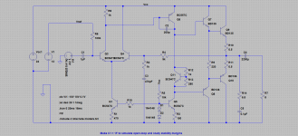
The resistor for the LTP isn't ideal, but its simple and works reasonably well. That can be elaborated on with a constant current sink.
The VAS current has to be high enough to satisfy the drive requirements of the driver + output transistor (it is after all their only source of current) and it also has to be high enough to charge and discharge both junction capacitance of the drivers and the deliberately added 200pF cap. If the current isn't high enough then the amplifier will exhibit 'slew rate limiting'. In other words when fed with a fast risetime signal, the output will be unable to follow it and will 'slew' slowly from one level to the next.
Slew rate - Wikipedia
(The VAS current and the output stage current are two separate things. Get the output current to low and you will see crossover distortion appear)
Mooly, thank you.
I'll build this amplifier on a protoboard to make some simple real world measurements, then, if all looks fine, solder it point-to-point.
As it is part of a learning curve, I won't bother making a PCB for it, for the moment.
I have a 3,9ºC/W heatsink and some insulation pads. I will try to use it for both output transistors. LTSpice shows just a few watts rms colector dissipation for each one at 3W output power.
Yes Mooly, I have both a bulb tester (for tube amp testing) and 30V/3A adjustable current-limited linear power supply, which now seems the best choice.
Thanks for the note.
Good idea suzyj. I'll try that out!
Just one more thing, is stability. I want to do it with LTSpice. To measurethe gain/phase margins, I have to look at the loop gain response. If I break the feedback loop, I get the open-loop response, but not the loop gain. How am I suppose to do it?
Yes Mooly, I have both a bulb tester (for tube amp testing) and 30V/3A adjustable current-limited linear power supply, which now seems the best choice.
Thanks for the note.
Good idea suzyj. I'll try that out!
Just one more thing, is stability. I want to do it with LTSpice. To measurethe gain/phase margins, I have to look at the loop gain response. If I break the feedback loop, I get the open-loop response, but not the loop gain. How am I suppose to do it?
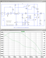
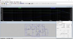
The way I do it is to DC couple to the input by replacing the input coupling cap with a voltage source, then give that a DC voltage so that your output (before the cap) is mid rail. Then increase the feedback resistor by a factor of ten and repeat tweaking the DC level to get back to mid rail, then again a couple of times.
Once you're at say 9Meg you've got a fair approximation of open loop. Then you run an AC sim to see what happens.
There are much more rigorous methods to do this, but I find this method gives me a reasonable answer without too much mucking about.
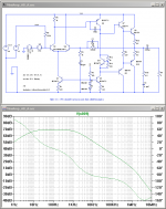
I find adding some capacitance across the feedback resistor in addition to the dominant pole helps stability. This is lead compensation and is very common in opamp design.
Attachments
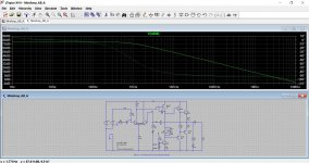
Apart from the method used by Suzyj, you can have a look at your LTSpice installation directory, there second example inJust one more thing, is stability. I want to do it with LTSpice. To measurethe gain/phase margins, I have to look at the loop gain response. If I break the feedback loop, I get the open-loop response, but not the loop gain. How am I suppose to do it?
examples/Educational/LoopGain.asc
You plot V(x)/V
by pressing CTRL-a in the plot window and entering the expression in the bottom input field.Matthias
There is video tutorial on the LT site about phase margin which I think will be similar to the method outlined by matze.
Solutions - LTspice: Stability of Op Amp Circuits
There are many approaches. I tried the LT method a little while ago but wasn't convinced I'd done it right at the time.
Solutions - LTspice: Stability of Op Amp Circuits
There are many approaches. I tried the LT method a little while ago but wasn't convinced I'd done it right at the time.
Attachments
- Status
- This old topic is closed. If you want to reopen this topic, contact a moderator using the "Report Post" button.
- Home
- Amplifiers
- Solid State
- Help with design for a simple low power audio amplifier