The source impedance presented to the input stage can be critical to stability.
Generally it seems to me that a low source impedance gets better stability.
An open input presents highest impedance and a shorted input presents lowest impedance. A large value RF attenuation capacitor presents a lower HF impedance.
Removing the input filter to examine the basic amplifier performance can make stability worse.
But these observations are from a non amplifier designer. I am a builder only.
Bread-boarding can introduce enormous loop areas. These will pick up interference and in the presence of high impedance can stimulate ringing or even oscillation.
I think you have two potential causes. If the power supply caps are too far away from the output transistors, add something like 100uF across the supply at the transistor collector connections. As little as 100mm has caused oscillations for me in the past.
The second issue is possibly related to the use of two BD139/BD140 output & driver transistors. They have high ft's in the 100MHz region and both will have significant gain at high frequencies so slight power supply lead inductances etc. could cause oscillations.
I recommended using TIP31/TIP32 output devices, these have fT's around3 Mhz and may give you less problem
A third cause is potentially related to power supply wiring and layout. Have you used "single star earth point" where the input earthy signals and power output stage grounds are commoned.
I also think that your layout is not best suited to amplifiers. Sorry.
For prototyping I have sometimes used plain PCB material, drilled holes to take the components and wired point-to-point following an estimated actual PCB layout. You need to keep inductance loops to a minimum, which means neatly wiring the transistors with as short a leads as possible. There seems to me to be scope for inductive loops with your current layout.
For prototyping I have sometimes used plain PCB material, drilled holes to take the components and wired point-to-point following an estimated actual PCB layout. You need to keep inductance loops to a minimum, which means neatly wiring the transistors with as short a leads as possible. There seems to me to be scope for inductive loops with your current layout.
And the winner is... the gentleman john_ellis 
A 100 uF decoupling cap solved the issue.
But you all guys helped me a lot, and I really appreciate your time and interest.
I've just done a test with an 8 ohm dummy load.
I get an undistorted sine wave up to 4.5W output power, at 360 mA current consumption (@ 24 Vdc).
So the 3W target power is achieved.
Of course my layout is poor... good "protoboarding" is not easy.
Thanks for all your critiques.
Now... is there any anything I can do to not risk my speakers??
As you might remember me saying, I've only built tube amplifier, and the output transformer is something I love, because it isolates the speakers completely from the circuit. No crowbar is needed
Protection from DC offset. Either an output capacitor, or a speaker isolating relay that can be triggered when an output error is detected.
These come long after you do extended testing into dummy loads, both hot and cold and warm and with some capacitance added across the dummy load.
Only when you are convinced the amplifier does not misbehave do you connect a cheap "test speaker".
These come long after you do extended testing into dummy loads, both hot and cold and warm and with some capacitance added across the dummy load.
Only when you are convinced the amplifier does not misbehave do you connect a cheap "test speaker".
Did you end up with capacitor coupled output (single power supply?)
If so that is a reasonable protection for a speaker, provided the working voltage is greater than the worst case (>24V). You could try a resistor in series with the speaker too, to start with. Use your dummy load for example.
Did you add the standard RC -LR networks? Many people refer to these as Zobel but as far as I can tell they are not true Zobels. The RC is a series pair connected across the output to ground (typically 10 ohms-47nF) the LR pair are in parallel, in series with the loudspeaker. Typical values 3.3uH//10 ohms)
For a 3W amplifier with a standard loudspeaker I would not think these necessary, but they may help, given your layout, in preventing stray oscillations.
After more than 15 minutes working, the OT's temperatures are stabilized at 55 vs 48ºC. Is these too much difference, or is it OK?
Also, there were some oscillations thickening a portion of the wave (as it is usual), and a 1uF capacitor conecting drivers emitters solved it. Don't know why, but I've seen it being used in other amplifiers.
Also, there were some oscillations thickening a portion of the wave (as it is usual), and a 1uF capacitor conecting drivers emitters solved it. Don't know why, but I've seen it being used in other amplifiers.
That breadboard layout looks like one of mine
You need to build the circuit up as per the finalised version. I'm not seeing the zobel network ? I think I can see a small ceramic cap going no where at the lower right.
You need a 0.1uF and 10 ohm (series connected) from the junction of the two resistors to ground. Connect the feedback up to this same point.
Try adding a bit of rail decoupling. Use a small cap of say 10uF on the top and bottom of the breadboard where you have ground and supply running parallel.
The zobel is in place. Just when I took the picture was out. A 10 ohm resistor is missing in the picture.
The bandwith is 50Hz-130kHz. Quite narrow on the bass side.
At 30 Hz, the voltage gain is halved (not the input signal, but the ratio of output to the inverting input, where the input caps should play no role).
The square wave test show bad low frequency response (as noted) and some overshot at 1 and 10 kHz. Tried capacitor shunting the feedback resistor, but nothing changed.
I finally connected it to a test speaker. Unfortunatelly it is a guitar speaker, so the frequency response is of no interest.
My observations are:
- Sound is nice (at least the frequencies which sound, hahaha )
- But it works only on low power levels (<150 mV ph-pk input). Else, the sound mutes at intervals (it goes out, then comes back, and so on). Output and input waves lose flattens (the signal generator and MP3 device output seems to be overriden).
- Also, even though output power is low, the dissipation is quite high (OT reached 65 ºC, and probably would have rise more; when a pure resistive 8 ohm load was about 55ºC)
- When I turn on the amplifier, a burst sounds from the amplifier. Not to high, but very evident.
Recommendations on how to proceed??
This is enough for one day!!
Thank you!
My observations are:
- Sound is nice (at least the frequencies which sound, hahaha
)- But it works only on low power levels (<150 mV ph-pk input). Else, the sound mutes at intervals (it goes out, then comes back, and so on). Output and input waves lose flattens (the signal generator and MP3 device output seems to be overriden).
- Also, even though output power is low, the dissipation is quite high (OT reached 65 ºC, and probably would have rise more; when a pure resistive 8 ohm load was about 55ºC)
- When I turn on the amplifier, a burst sounds from the amplifier. Not to high, but very evident.
Recommendations on how to proceed??
This is enough for one day!!
Thank you!
Enough for one day
It could interesting to see how the amp behaves with less feedback. This will make the amplifier more sensitive though.
Try increasing the feedback resistor from 9k to something nearer 47k.
You can also experiment with reducing the LTP tail resistor a little. 12 k is it now ? Try 8k2.
(We can have a more detailed look tomorrow)
Your burst of sound suggests that your amplifier is still prone to oscillation. Your other description of the sound "muting" sounds like what was called "motorboating". Motorboating was often caused by low frequency oscillations but can also be caused by high frequency oscillations, leading to rectification in the input transistor, which alters the D.C. conditions and so on.
SO perhaps the first thing I would try is to connect an input filter of say 1k series resistor and a 100pf capacitor across the input transistor base to ground. This is not really to act as a filter in this case - though often used in many designs to be so - but to control the input impedance at high frequencies when your layout may be prone to impedance variations.
The other thing to watch for is earthing. You may need to take special care of where the earth return is from your signal generator to the input (and common ground connection) as, as we discussed in the earlier posts, not optimal layout makes oscillation more likely.
What does your scope show when the outputs are low - can you see any signs of trouble in the traces in the periods of low output?
By the way, your poor low frequency response is probably due to the relatively small capacitance of the output capacitor. Once your oscillation problems are solved, you should try increasing this to perhaps 10mF -if you need a better LF response.
Last edited:
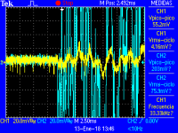
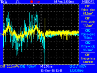
john_ellis, the burst became much more subtle once I rewire the grounds a little bit better.
The muting still happends, even with the series 1k8+100pF from input base to ground.
I attached some scope captures exactly at the point the sound muted/un-mutted. I see no evidence of evil there
But, when output voltage raises from 0.1Vrms, mutting begins to happend.
Mooly, I already lowered the tail resistor (exactly to 8k2!). I did that to be able to work with lower supply voltage (18Vdc), else the output just faded out (I suppose I ran out of current, because non-inverting transistor cutoffs).
Yes, there's quite a bit of feedback. I'm used to not using more than 20 dB of GNFB. This one could be over 45 dB.
By the way, I'm always using 24Vdc as in the LTSpice schematic. The 18Vdc was just some testing I wanted to do.
Attachments
Better wiring, more filtering capacitance,and it is finally working at good volume on my guitar speaker!!
I just did a some audio tests with music, from a MP3 portable device, for more half and hour, and getting about 5V peak-peak output, I'm surprised with the volume it's putting out. Under 0.5W output power, and it sounds quite load! Maybe my speaker is very sensitive... or maybe 1W is more than I thought.
Obviously, the OT temperature is very low, even with these little 15ºC/W heatsinks.
And the noise floor is under 30 mV p-p at the output. I hear absolutely nothing when pausing the music.
It seems to work fine and not willing to do any harm to the speaker.
So I'm going to add some more capacitance at the output, and test with "music" speakers, not really hi-fi, but decent quality. Wish me luck
By the way, are there any other safety test recommendations?
Last edited:
Many speakers have a sensitivity between 85dB and 90dB per watt.
That is loud when you are only a couple of metres away.
A guitar speaker intended for PA duty could be much more sensitive.
Testing safely:
use a dummy load resistor and add on a range of small plastic film capacitors to check how unstable the amp becomes as you step the cap from 10nF to 1000nF.
That is loud when you are only a couple of metres away.
A guitar speaker intended for PA duty could be much more sensitive.
Testing safely:
use a dummy load resistor and add on a range of small plastic film capacitors to check how unstable the amp becomes as you step the cap from 10nF to 1000nF.
Better wiring, more filtering capacitance,and it is finally working at good volume on my guitar speaker!!
That's good to hear. Layout and wiring is very critical as you are finding out.
There is a good thread here that will let you test how much voltage swing you need for your normal listening levels at home. You might be surprised
A Test. How much Voltage (power) do your speakers need?
Sorry AndrewT, it might be a stupid question but, the caps your're talking about are meant to be placed in series with the load, or in parallel to ground?
A cap parallel to your dummy load adds some reactance to the load and the amplifier usually starts to misbehave with some capacitances.
Adding a cap in series does not have that effect. It just restricts the frequency range over which the dummy load gets to draw some current.
That exactly what the Output Zobel does. It only passes (significant) higher frequency current and no DC current.
- Status
- This old topic is closed. If you want to reopen this topic, contact a moderator using the "Report Post" button.
- Home
- Amplifiers
- Solid State
- Help with design for a simple low power audio amplifier