Thanks, I've done the baffle step sim, it does change things somewhat, as expected. I also remembered I had a motorola piezo horn tweeter in the garage, so tried to do an impedance measurement.
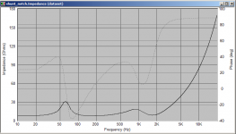
I'm not sure if there is a problem with my reference resistor being too low (8.1 ohms) but the impedance plot starts at about 64K and works it's way down to 100 ohms at 20Khz... If that is typical of a piezo horn then what I posted before just won't work.
So no more to post just yet")
Tony.
I'm not sure if there is a problem with my reference resistor being too low (8.1 ohms) but the impedance plot starts at about 64K and works it's way down to 100 ohms at 20Khz... If that is typical of a piezo horn then what I posted before just won't work.
So no more to post just yet
Tony.
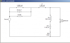
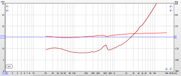
OK Getting somewhere now Note that until I do the tweeter however, this is just a progress report.
The blue curve is the adjusted for full baffle step. Black is with the crossover network (as you can see I've done full BSC!, but as this is a boom box that is probably best).
I took the same aproach to dealing with the baffle step that I did with my MTM's ie a notch filter. Perhaps not the most conventional approach but it worked ok for them, and seems to work ok here.
The first couple of iterations had an unacceptably low impedance around 2Khz (about 3 ohms) this variation has no such problem. I've also made sure that all caps and coils are standard values.
I changed to a 4th order L/R acoustic slope.
I've done a bit of research on peizo's and if I change the position of the notch filter then a normal type crossover should work. I will use the impedance curve from my one or another I can find online, as the resistor in parallel with the tweeter will be the dominant thing in determining the filter characteristics. It actually looks like the impedance curve of the tweeter is not that important afterall.
another installment tomorrow perhaps
Note that I think that this baffle step adjusted curve was with a 53Hz tuning (spliced in) for the lower part of the curve. 53Hz seemed to be the best I could find in between the original 42Hz I was thinking about and Chris' 60Hz tuning.
Tony.
Note that until I do the tweeter however, this is just a progress report. The blue curve is the adjusted for full baffle step. Black is with the crossover network (as you can see I've done full BSC!, but as this is a boom box that is probably best).
I took the same aproach to dealing with the baffle step that I did with my MTM's ie a notch filter. Perhaps not the most conventional approach but it worked ok for them, and seems to work ok here.
The first couple of iterations had an unacceptably low impedance around 2Khz (about 3 ohms) this variation has no such problem. I've also made sure that all caps and coils are standard values.
I changed to a 4th order L/R acoustic slope.
I've done a bit of research on peizo's and if I change the position of the notch filter then a normal type crossover should work. I will use the impedance curve from my one or another I can find online, as the resistor in parallel with the tweeter will be the dominant thing in determining the filter characteristics. It actually looks like the impedance curve of the tweeter is not that important afterall.
another installment tomorrow perhaps
Note that I think that this baffle step adjusted curve was with a 53Hz tuning (spliced in) for the lower part of the curve. 53Hz seemed to be the best I could find in between the original 42Hz I was thinking about and Chris' 60Hz tuning.
Tony.
Attachments
Shaolin, how adventurous are you feeling? Would you be willing to sacrifice a 3.5mm to 3.5mm audio cable to make some test euqipment??
On looking more closely at the PH25 tweeter it isn't a piezo like I thought. It has a voice coil and magnet so I was barking up the wrong tree. In order to do the tweeter crossover properly I would really need an impedance plot for this particular tweeter, and I've turned up zilch on google.
The impedance cable here --> Cables on Claudio's page is what you need.
Add a sound card that has line in and out, and REW available here --> REW - Room EQ Wizard Room Acoustics Software and you can make an impedance measurement of the tweeter relatively easily.
There is a bit of playing around with levels till you get it right but it is not too hard. I can post some screenshots if you like.
Without a proper impedance plot for the tweeter I am basically stabbing in the dark with respect to the simulated crossover for the tweeter.
Tony.
I use 8 ohms in mine (and I think it is a 5W) Though for impeadance measurements a lower wattage should be fine. Try and use a 1% resistor if you can. Depending on your sound card it may be better if the resistor is a bit higher in value. anything between 10 and 100 ohms is probably ok. You put the value of the resistor into REW and it uses it as a reference to calculate the impedance of the driver based on the difference between the left and right channels.,
Tony.
Tony.
Tony.
Tony.
Hi Chris, yes the ESP line level BSC is an option. There may be a need for a buffer though? I guess it depends on the input impedance of the amp...
The passive line level option will address the majority of the issue (WRT level) but it will probably still have a hump around 1Khz... It would be necessary to do actual measurements with the BSC ciruit in place to work out what compensation (if any) was needed. That was the main reason I did it as passive, as it gives a fairly good chance to get as flat a response as possible without actual measurements.
shaolin, when doing the impedance measurements you only need a low level on the soundcard. Try starting at say 10% output volume. I set the recording level to 50%
Tony.
I'm using my computer's onboard sound hardware, and after struggling with a feedback loop for a while I managed to get a semi-normal curve after calibration.
Looking at the online help for the program, the next step is level adjustment. When I check levels the returned curve is way off - much too loud. Also, when I tried my new impedance cable, I got the test tone going through the tweeter, but measurement never really completed - I got an error / warning message saying that the level was far too low (-99db) and that I should check to see if my right / left channels were reversed. I'm pretty sure the channels were fine.
Perhaps I'll try to get a cheap(ish) sound card and give it a try not running off my motherboard.
Any thoughts?
On borad sound should be ok for impedance measurements. I actually can't remember if I calibrated (I think I did) but I definitely didn't worry about the spl calibration.
I've used trial and error to work out what settings seem to give the best measurements. For my sound card, I set the record levels to 50% Line in to about 60% and volume to around 10% I think.
If your card has an option for record without monitoring then make sure it is ticked.
Did you go into the preferences for REW and make sure that what it has for playback and recording seems to be what you expect? relying on windows defaults may not work.
I'll have a look at REW tonight and see if I can see anything that I take for granted that might be throwing a spanner in the works
Tony.
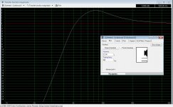
OK I have had a look at REW. Apparently I did perform the calibration as I have a cal file enabled. I haven't done an spl calibration though, and it is not necessary for impedance measurements.
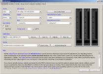
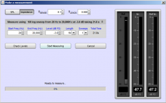
I've attached a screenshot of the settings I use for doing the impedance measurement. and also a plot that I just did of my little bass reflex project that has stalled....
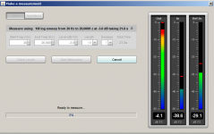
Also I attached a picture of how the levels looked when I did a check levels.
You should get a pretty smooth result like the attached.
My levels were set at 50 for recording, 50 for line in, 20 for volume. All other inputs muted.
Are you using the java drivers? I'm using ASIO but they were a PITA to set up! What is working for my Audigy II sound card is also attached. Java drivers should be easier to get going though.
When I measured the tweeter the other night it took me a while to get things working. In the end I realised that the problem was I had my input and output mixed up The speaker still made noise, and the levels sort of showed but the reference level showed nothing.
I think by default it only outputs on one channel too, so if you are getting nothing on the recording levels try switching the input channel
Tony.
I've attached a screenshot of the settings I use for doing the impedance measurement. and also a plot that I just did of my little bass reflex project that has stalled....
Also I attached a picture of how the levels looked when I did a check levels.
You should get a pretty smooth result like the attached.
My levels were set at 50 for recording, 50 for line in, 20 for volume. All other inputs muted.
Are you using the java drivers? I'm using ASIO but they were a PITA to set up! What is working for my Audigy II sound card is also attached. Java drivers should be easier to get going though.
When I measured the tweeter the other night it took me a while to get things working. In the end I realised that the problem was I had my input and output mixed up
The speaker still made noise, and the levels sort of showed but the reference level showed nothing. I think by default it only outputs on one channel too, so if you are getting nothing on the recording levels try switching the input channel
Tony.
Attachments
I put in a cheapo Sound Blaster Audigy 2 SE card and had some success with the setup. I'm not sure if I've managed to get anywhere with the impedance graph.
link to tweeter measurements are attached.
Thanks!
https://www.wetransfer.com/download...df4de93218d4910bf425632020130608230446/4ab140
link to tweeter measurements are attached.
Thanks!
https://www.wetransfer.com/download...df4de93218d4910bf425632020130608230446/4ab140
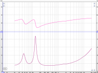
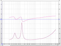
Hi Shaolin, you are almost there. It looks like you have the left and right channels (recording) reversed. The impedance is reading higher and the phase -180 degrees as a result.
I just tried myself to make sure this was the problem. See attached graphs. The one with the phase above the impedance plot and lower overall impedance is the correct one.
Try reversing which channel is on the reference resistor and which on the driver, and I think you should be on the money.
Tony.
I just tried myself to make sure this was the problem. See attached graphs. The one with the phase above the impedance plot and lower overall impedance is the correct one.
Try reversing which channel is on the reference resistor and which on the driver, and I think you should be on the money.
Tony.
Attachments
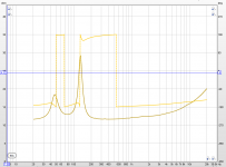
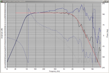
Hi Shaolin. I'm interested in that woofer measurement, it doesn't fit with what I would have expected. Is the driver in the original box. ~21L sealed (0.75 cft)?
I've attached your measurement, and also what the sim predicts the impedance should look like in a 21L sealed enclosure (with heavy stuffing).
The main oddity is the lack of an impedance peak around 77Hz. There also seems to be something going on around 600Hz, probably a resonance of some sort, but I'm not sure what. If it was ported I'd say possibly a port resonance, but otherwise it could be a cabinet one. I suspect it is unlikely the actual driver.
A measurement of the driver in free air will show whether it is inherent to the driver or something to do with the box. A free air measurement can be done by clamping (or screwing) the driver to an open frame of some sort, or suspending the driver from a wire in mid air.
what's the brand and model number of the other tweeter?
Tony.
Attachments
Last edited:
- Status
- This old topic is closed. If you want to reopen this topic, contact a moderator using the "Report Post" button.
- Home
- Loudspeakers
- Multi-Way
- Help with bass response on my first build...