INput Cap
Hello, Just wondering. Is it possible to change the input cap (instead of the suggested 2.2 uf) so that it starts rolling off a little earlier, Say 120hz *like a high pass filteR,
Is this possible? Or is it better just to add a passive line level xo?
Thanks for any help
Hello, Just wondering. Is it possible to change the input cap (instead of the suggested 2.2 uf) so that it starts rolling off a little earlier, Say 120hz *like a high pass filteR,
Is this possible? Or is it better just to add a passive line level xo?
Thanks for any help
 ')
')
panomaniac said:
As you stated, the best solution is to drive both the T-Amp and the sub amp from an active preamp. Buy one or make one, there's not much to it.
On the subject of preamps. Does anybody know of a preamp that has not only multiple inputs, but multiple outputs.
Here's what I'm trying to do. I have multiple t-amps that I would like to drive off the same source(s). 2 t-amps are used to bi-amp 1 pair of speakers and 2 others I use for other speakers in other rooms.
The ideal pre-amp for me would be a 12 volt pre-amp with a couple of inputs and 4 or so outputs.
Does anybody know of such a preamp?
Thanks,
Wow, that's ugly.
Start by cleaning off all that flux and burned junk with rubbing alcohol.
Most of the time when you burn a pad you can scrape back the mask very carefully with an X-Acto knife to reveal shiny copper on the trace(s) leading to it. Using a single strand of some multi-strand wire, you can theoretically bridge any burnt places. Tape the wire in place, hit with flux, and with a TINY dab of solder on the tip of the iron, hit it for no more than a second. This should do it. Repeat on other end.
You say you knocked off a component. Do you think it's in good enough shape to work if you can get is reconnected? What is it? I don't have that model or a photo handy.
OK, I have to say this: next time, try a soldering iron instead of a blowtorch. Seriously, those things are tiny and need very little heat if you have a sharp iron tip. Getting good magnification and bright light is half the battle. I have found a flux pen helpful as it makes the solder flow quicker. And don't do what I did and try to use silver solder, as it melts at a high temperature and doesn't flow and stick as well as the lead/tin eutectic.
--Buckapound
Thanks for the reply and advice!
Yes it is ugly, my 15 W iron stopped working in the middle of the project and so I switched to my 30 W iron with the results here and I was using silver solder... So out to get a flux pen and lead solder. Hopefully my third RS 15 W iron will keep working for a while longer.
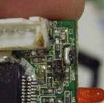
Actually, I snapped the component in half so it is no longer usable but I have looked at another one of these boards and it appears neither to be a resistor nor a capacitor. On the board it was marked L1 and it looks identical to the piece to the left of C4 in the photo, that is marked L2. These are boards from Sonic Impact amps, the last version of the first generation I suppose you could call them.
Can one actually attach SMCs???? Wow these things are so tiny, I can't imagine that is done with a conventional soldering iron....
Yes it is ugly, my 15 W iron stopped working in the middle of the project and so I switched to my 30 W iron with the results here and I was using silver solder... So out to get a flux pen and lead solder. Hopefully my third RS 15 W iron will keep working for a while longer.
Actually, I snapped the component in half so it is no longer usable but I have looked at another one of these boards and it appears neither to be a resistor nor a capacitor. On the board it was marked L1 and it looks identical to the piece to the left of C4 in the photo, that is marked L2. These are boards from Sonic Impact amps, the last version of the first generation I suppose you could call them.
Can one actually attach SMCs???? Wow these things are so tiny, I can't imagine that is done with a conventional soldering iron....
L2 would be an inductor, and should be no problem taking it off another board if you can manage.
What you really need is a temperature-controlled soldering station with interchangeable tips. for the surface mount stuff, you need a point that's fine enough to kind of lay right down in the angle between the end of the part and the board. If your RS iron has a pencil-pointy tip, you should be able to work with it for now.
Look around the web; there are several good tutorials if you search "surface mount soldering tutorial."
You too can solder small parts. Using the stuff from my previous post plus a sharp pair of tweezers, here's how I do it--and I'm far from being an expert. Dab some fluxon the board where'e you're soldering. Get the iron hot, and add a teensy dab of solder to the tip, and place a tiny spot of solder on the pad(s) where your part will go. Now, hold the part in the middle and place it in position, then just touch the iron to that corner formed by the end of the part and the pad and the solder should flow and make contact with the part. Don't hold it for more than a second or possibly two, and don't worry if it's not a very good joint or if the other end is sticking up a bit as long as it's sticking. Then take the tweezers and while pressing gently on the top of the part, repeat at the other end, perhaps with a tiny bit of solder on the iron tip, which should make for a nice joint. Then, go back and add a bit of solder if needed and reflow the first end for a good joint.
The most important thing is not to spend too much time on any one joint. If you're doing things right, you won't have to. Once the plastic and resins start to cook, the board becomes hard to deal with, as you found out.
If you have other projects for which you need a small Tripath amp, the 41hz.com Amp6 is pretty easy to solder, and if you're ordering things from them you can order their inexpensive surface-mount soldering practice board. Of course, if you've got any kind of broken electronics, there should be plenty to work with.
Let us know how it all turns out.
--Buckapound
help with burned t amp board - the demolition derby continues!!!
Well - I think I just blew the chip on the better of my two t amps when I caused a spark while testing the DC Jack of my new project - so:
I will need to transfer the following SM parts from the destroyed board to the semi-destroyed board:
MIA:
L1
And the new MIA pieces due to dropping of the board, an aggressive 3rd hand tool which kept on slipping and the attack on the white plastic plug :
C1
C2
And on the bottom of the PCB:
C58
Questions:
- Will the spark that presumably knocked out my chip have effected the SM parts that I would like to transfer to the other board?
- Do the parts that need to be transferred: L1, C1, C2 and C58 need to be mounted with attention to polarity? If so, how?
- Is there a way of testing my chip to see if it has been destroyed? I did plug in and power up the project:
- The On/Off switch worked
- The new power supply Cap did receive power
- The Pot went from 0 - 50K on both channels
- The Speaker wires were fine from the Binding Posts to the PCB.
- The RCA inputs and connections were fine too.
- No sound
- No lit LED
- The original mini-jack input and DC jack were removed from the board but I wouldn't think that was causing the problem...
Ideas?
- Also fragments of MIA pieces on the still on the pads (visible in the photos) shouldn't cause problems with the pieces to be mounted over if I blob them first, right?
- I am using an diode on the DC input to stop problems with battery polarity knocking out the chip while playing the amp outside, (it didn't help on my work area though") ) - that shouldn't have caused any problems, right?
) - that shouldn't have caused any problems, right?
Thanks in advance!!!!
Steve
Well - I think I just blew the chip on the better of my two t amps when I caused a spark while testing the DC Jack of my new project - so:
I will need to transfer the following SM parts from the destroyed board to the semi-destroyed board:
MIA:
L1
And the new MIA pieces due to dropping of the board, an aggressive 3rd hand tool which kept on slipping and the attack on the white plastic plug :
C1
C2
And on the bottom of the PCB:
C58
Questions:
- Will the spark that presumably knocked out my chip have effected the SM parts that I would like to transfer to the other board?
- Do the parts that need to be transferred: L1, C1, C2 and C58 need to be mounted with attention to polarity? If so, how?
- Is there a way of testing my chip to see if it has been destroyed? I did plug in and power up the project:
- The On/Off switch worked
- The new power supply Cap did receive power
- The Pot went from 0 - 50K on both channels
- The Speaker wires were fine from the Binding Posts to the PCB.
- The RCA inputs and connections were fine too.
- No sound
- No lit LED
- The original mini-jack input and DC jack were removed from the board but I wouldn't think that was causing the problem...
Ideas?
- Also fragments of MIA pieces on the still on the pads (visible in the photos) shouldn't cause problems with the pieces to be mounted over if I blob them first, right?
- I am using an diode on the DC input to stop problems with battery polarity knocking out the chip while playing the amp outside, (it didn't help on my work area though
) - that shouldn't have caused any problems, right?Thanks in advance!!!!
Steve
Attachments
Hi Steve, it's been a while since I played with one of these and I haven't had one of the MKII Sonic boards but...
If you have continuity from your power to the on-board cap and the LED is not lighting up then it does sound that a reversed polarity has knocked out the chip I'm afraid. Audio 1st's post shows the fuses that could have gone on the speakers... worth checking.
However.... there is one posibility which has happened to me in the past.
Check the cap that supplies pin 36 (CPUMP). If that has blown (continuity across it) then it just needs replacing.
Good luck
Oh yes, the parts you mention have no polarity.
Attachments
help with burned t amp -
Thanks Lostcause!
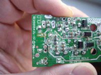
After looking at Audio1st's post, I checked the fuses on Board 1, which got the spark and has the presumed bad chip. F81, F82 and F84 all had continuity across them. However, when I tested Board 2 which as far as I know should be pristine, with regard sparks at least, it registered the same. Interestingly, F83 is showing no continuity on either board.
I noticed that Panomaniac questioned whether they are fuses:
Another thing, when I test the chip, pardon my ignorance, but how do I tell which side is up and which is down?
Steve
Thanks Lostcause!
After looking at Audio1st's post, I checked the fuses on Board 1, which got the spark and has the presumed bad chip. F81, F82 and F84 all had continuity across them. However, when I tested Board 2 which as far as I know should be pristine, with regard sparks at least, it registered the same. Interestingly, F83 is showing no continuity on either board.
I noticed that Panomaniac questioned whether they are fuses:
Post #101 Thanks for the photos, the board does look better. Are you sure those are fuses? Might they not be Ferrites for RF noise suppression?
Another thing, when I test the chip, pardon my ignorance, but how do I tell which side is up and which is down?
Steve
Hi Steve, yeah, Pano may be right, I've never had one of these boards so I can't check.....
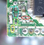
Anyway, the picture is from the black resin side and you can see the dot in the top left corner.
Trace pin 36 until it meets a small cap and then test that for continuity.
EDIT:
OK just looked closer.. it's C9 right next to the pin.
Other than that it's not looking too good I'm afraid
Anyway, the picture is from the black resin side and you can see the dot in the top left corner.
Trace pin 36 until it meets a small cap and then test that for continuity.
EDIT:
OK just looked closer.. it's C9 right next to the pin.
Other than that it's not looking too good I'm afraid
Finally got mine yesterday... Ya I know I'm way behind the curve. It's the newer board. I have coils on mine to the speaker outputs. A ferrite doughnut with the speaker wires looped thru twice. I suppose it's a low pass filter for cutting upper frequency noise.
Anyone else do anything with those? I'm considering ditching the volume control all together. I had some 2uf Solens laying around & gonna bypass with a Sidereal .01 uf (yea old skool).
I've been digging around, I thought there were a few more mods besides the input caps & using a better supply (besides swapping hardware)? If anyone one can point me in a direction... I've already looked at M.Madis site. Unles I've missed something.
Thanks
Welcome to the cult, or whatever this is. Definitely good sound for cheap.
Volume control you either need or don't, so get rid of it if you don't need it.
The biggest other area of improvement is replacing the reservoir cap (C10?)m the biggest cap on the board. You should be able to at least double the value in the same footprint. Look for the "low ESR" or "low impedance" type. Panasonic FMs are often recommended, but Nichicon and others have lines of good grade caps too. There is room on the board to add even more capacitance, but as I recall from the discussions usefulness tops out at about 5-10,000 uf, and the closer to the chip the better.
I replaced the main output inductors, but didn't notice a dramatic effect. I don't think the ferrite rings can hurt anything. Some models have a small cap on the output (.1uf?), which also filters out HF hash.
Depending on your source device it might be worth changing the values of the feedback resistors, which changes the gain. I don't have the specifics, but I think the SI comes fairly low in gain, so if you're using an iPod, you might get a little louder sound by upping the gain. Then you can join the hi-wire world of unsoldering and soldering surface mount components.
Check back on the threads, There's a ton of discussion on the specifics.
Oh, and be aware that these things take a week or two of use to burn in and sound their best.
--Buckapound
"Depending on your source device it might be worth changing the values of the feedback resistors, which changes the gain. I don't have the specifics, but I think the SI comes fairly low in gain, so if you're using an iPod, you might get a little louder sound by upping the gain. Then you can join the hi-wire world of unsoldering and soldering surface mount components."
That ould be nice to up the gain a bit, anyone else try that mod?
As far as soldering SMT, I spent 5 years repairs computer motherboards under a microscope. The only issue is these tried old eyes can't do it without now... I use a magnifier & an Intel QX3 kids USB microscope to help locate the parts...
Ill definitely be changing out the big cap too. So you noticed no difference w/ w/o coils on outputs. Maybe I should put a scope on it to see if I notice anything.
I want this as clean & neutral as possible. you might say I have a bet going as to how far I can take it.
I found a old computer PS that I started to pull apart. Found some 470Uf & a couple of 2200 uf caps that could work. Nothing fancy, just using what I have hanging around in the garage.
I removed t form the case & replaced all the wires except ribbon cable with a higher grade of wire & gauge. Can't believe they are using 24 AWG wire on this. That stuff just about breaks off when trying to move things around.
Listened to it w/o the output caps, yep they definitely help on the hash. I have a PS from a old mobile audio display that I'm using. I adjusted it to 13V. That seems to give a bit more headroom.
Cap mod is next then PS caps next. I think I'll try the 470uf 1st & then maybe the 2200 uf after that. I have s couple of memory heat sinks I can put on the chip I may attach them to the ground plane (large pad under chip) I think that would draw more heat away than trying to attach to the plastic case.
newbie questions for modification
Hi,
I have this amplifier board and I'm looking to do the stealth modifications to it. I have a couple questions since I'm a newbie. Looking at the auricaps, I noticed that the 2.2
f caps come in 200V and 400V. Which do I need for this application? I think I need the 200V, but I want to be certain.
Hi,
I have this amplifier board and I'm looking to do the stealth modifications to it. I have a couple questions since I'm a newbie. Looking at the auricaps, I noticed that the 2.2
HTML:
& #956;- Status
- This old topic is closed. If you want to reopen this topic, contact a moderator using the "Report Post" button.
- Home
- Amplifiers
- Class D
- Help Wiring a Replacement Potentiometer for Sonic T