hi all
The last post for my T amp. i have tried to shield the caps and wires, noise reduced a bit (not much) and I actually couldn't get rid of the background noise. So will be please to use the water pipe for grounding.
I posted my mod detail, drawing on Audo1st dia. Will try to find a digital camera to post pics when possible.
Thanks for your advice sofar.
Attachments
Lostcause said:
I suppose you just need to use the resistors you jumped in with?
Un-solder from the caps and solder that end to the board to complete the circuit as it was? The traces/leads will increase the chance of RF pick-up but it may be OK?
I have the same problem, but I do not really understand the answer you gave. I still have R1 and R2 and I "may" be able to re-solder them, if it is neccessary to put them back. Your help would be appreciated. By the way do you know what vlaues R1 and R2 are ?
Better if you put the originals back, and a lot tidier!Puffin said:I have the same problem, but I do not really understand the answer you gave. I still have R1 and R2 and I "may" be able to re-solder them, if it is neccessary to put them back. Your help would be appreciated. By the way do you know what vlaues R1 and R2 are ?
To be honest, I've done both now and can't really tell much difference because I shield everything when using the classic approach. changing over to the stealth method is only really needed if you have noisy inputs.
R1 & R2 are 20K but the feedback resistors (R4&5) are 35K, that's why I frefer to use the classic with 35K resistors to jump in with.
If I was pushed for an opinion then my first board with R4&5 replaced with 20K's (R1&2) and 20K resisors to jump in with, is my board of choice....not much in it though.
genki said:The last post for my T amp. i have tried to shield the caps and wires, noise reduced a bit (not much) and I actually couldn't get rid of the background noise.
Sorry to hear that but (gloat gloat) mine is back to total silence since rehousing. I've used one of the extruded aluminium Hammond 1455N cases, the amp pcb & caps are mounted on a piece of coppered circuit board, copper up. Case and copper both connect to power ground, signal grounds meet at the pot. Plan B was to wrap the caps in foil pressed against the board but I won't bother now.
Nothing in the system connects to safety earth and the only screened cable inside the amp is from rear phonos to front pot.
One job left, put a 2k resistor in series with the new blue LED, it's a bit of a dazzler.

May be I'll wait until some of you have better solution to the problem (sorry but I'm not an EE to have any good idea to this). i have thrown away the original R01 and R02. I use a wooden case (not a metal case), do you think it is the problem? Any way, if I connect the outter tags ( the interconnected tags, according to the dia) of the input jacks to water pipe, then it is silent. Do you think it can cause any damage or problem to the system (eg, the life expectancy) in the long run?
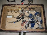
I attached here some pics of my amp
here is the inside, quite chaostic, but i am bad at this
I attached here some pics of my amp
here is the inside, quite chaostic, but i am bad at this
Attachments
cpemma said:
Sorry to hear that but (gloat gloat) mine is back to total silence since rehousing. I've used one of the extruded aluminium Hammond 1455N cases, the amp pcb & caps are mounted on a piece of coppered circuit board, copper up. Case and copper both connect to power ground, signal grounds meet at the pot. Plan B was to wrap the caps in foil pressed against the board but I won't bother now.
Nothing in the system connects to safety earth and the only screened cable inside the amp is from rear phonos to front pot.
One job left, put a 2k resistor in series with the new blue LED, it's a bit of a dazzler.
Hi CPemma
Could you please post your dia or some pics of your mod so that I can see clearly what you've done. Could be useful for me.
Thanks in advance
genki said:Hi CPemma
Could you please post your dia or some pics of your mod ...
It's just the stealth mod from Panomaniac's site (note the C4 cap bridge
 ) & C10 cap change (to 470uF) with a 1000uF low-ESR on the back of the power socket. Plenty of room for a bigger stiffener next time I order some stuff, but I'm happy with everything but the volume limitation (big room and ordinary/low efficiency speakers).
Yellow wire on the copper ties to case, copper ties to power ground, not quite star but WFM. The white LED wire is not attached to the cap.
An externally hosted image should be here but it was not working when we last tested it.
Sorry about image size, can't find the code for attachments.
Mini-jack
I think I see your problem. When the mini-jack is connected to the board and there is nothing plugged into it, I think the input is shorted out. Try plugging a something into the mini-jack input, and if that works, you might consider removing it from the board. It's a pain in the neck, but possibly worth it.
Jeremy
genki said:May be I'll wait until some of you have better solution to the problem (sorry but I'm not an EE to have any good idea to this). i have thrown away the original R01 and R02. I use a wooden case (not a metal case), do you think it is the problem? Any way, if I connect the outter tags ( the interconnected tags, according to the dia) of the input jacks to water pipe, then it is silent. Do you think it can cause any damage or problem to the system (eg, the life expectancy) in the long run?
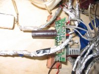
Hi genki, is all that silver foil grounded? if not it will make your problem worse. Are the outer tags of the input jacks connected to the boards ground?
Re: Mini-jack
The PCB power input socket's switch cuts the battery negative lead when external power is plugged in (so you don't charge dry cells), the "short" with nothing plugged in is external supply negative to battery negative. No switching with the stereo jack AFAICS, WFM with both left and unused.
Best T-amp mod with the Hammond case I've seen is zanash's lighting effect, they're very nice cases to work with.
Diomedian said:I think I see your problem. When the mini-jack is connected to the board and there is nothing plugged into it, I think the input is shorted out.
The PCB power input socket's switch cuts the battery negative lead when external power is plugged in (so you don't charge dry cells), the "short" with nothing plugged in is external supply negative to battery negative. No switching with the stereo jack AFAICS, WFM with both left and unused.
Best T-amp mod with the Hammond case I've seen is zanash's lighting effect, they're very nice cases to work with.
cpemma,
I'm not sure if this is the case for all T-amps but on at least one of the units that I measured, when there was no 1/4 inch connector plugged into the stereo input, I got 0 ohms from input to ground. Try it anyway - it couldn't hurt. This solved the "no sound" problem on a friend's board.
Jeremy
I'm not sure if this is the case for all T-amps but on at least one of the units that I measured, when there was no 1/4 inch connector plugged into the stereo input, I got 0 ohms from input to ground. Try it anyway - it couldn't hurt. This solved the "no sound" problem on a friend's board.
Jeremy
The right pot?
Hi guy's, just playing with my new amp6 and I've put in a 100K pot....the only one I have to hand. The thing is, there is a faint hum on both channels that increases with volume until I reach maximum...then it dissapears.
Would the value of the pot play any part in this? Or could it be a bad pot?....or is it something completely different?
My inputs are shielded but I don't think that has anything to do with it, or the hum wouldn't go at full vol
Any thoughts chaps?
Lee
Re: The right pot?
'Thanks Jeremy but I don't really get what is the mini jack. If it is the DC in jack, then I've already removed it from the board.
To audio1st
no, not at all. So the idea now is try to connect the outter tags of the input jacks to the board ground, right? If so I will try it. What I do now is connect it to the water pipe.
To Lee
From my experience, I can tell it is not the pot. I previously used a 50k pot and I had the same problem as I had with the 100k ALPs pot now. It is the same as you sad. May be you can try a 50k and see the difference.
To Jeremy:Diomedian said:I think I see your problem. When the mini-jack is connected to the board and there is nothing plugged into it, I think the input is shorted out. Try plugging a something into the mini-jack input, and if that works, you might consider removing it from the board. It's a pain in the neck, but possibly worth it.
Jeremy
'Thanks Jeremy but I don't really get what is the mini jack. If it is the DC in jack, then I've already removed it from the board.
audio1st said:
Hi genki, is all that silver foil grounded? if not it will make your problem worse. Are the outer tags of the input jacks connected to the boards ground?
To audio1st
no, not at all. So the idea now is try to connect the outter tags of the input jacks to the board ground, right? If so I will try it. What I do now is connect it to the water pipe.
Lostcause said:Hi guy's, just playing with my new amp6 and I've put in a 100K pot....the only one I have to hand. The thing is, there is a faint hum on both channels that increases with volume until I reach maximum...then it dissapears.
Would the value of the pot play any part in this? Or could it be a bad pot?....or is it something completely different?
My inputs are shielded but I don't think that has anything to do with it, or the hum wouldn't go at full vol
Any thoughts chaps?
Lee
To Lee
From my experience, I can tell it is not the pot. I previously used a 50k pot and I had the same problem as I had with the 100k ALPs pot now. It is the same as you sad. May be you can try a 50k and see the difference.
total beginner, I am...
don't know how to read the diagrams... but I have the coldheat solder gun and willing.
1. is there a website where I can get the replacement parts?
2. is there a picture for step by step, (ie dummy guide style)
I thank all.
gychang
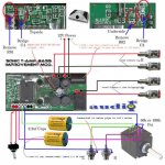
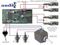
audio1st said:Here is a Sonic T Amp, Bass Mod' dia' if anybody is still in need of it ?.. Done to death I know..
don't know how to read the diagrams... but I have the coldheat solder gun and willing.
1. is there a website where I can get the replacement parts?
2. is there a picture for step by step, (ie dummy guide style)
I thank all.
gychang
Re: Re: fried?
HansR, how does one insulate speaker terminal?
thanks,
gychang
DEQ+TheEnd said:
Most common error people do when reboxing the SI is that they forget to insulate the speaker terminals in they're new and stylish metal box.
regards
HansR
HansR, how does one insulate speaker terminal?
thanks,
gychang
Re: total beginner, I am...
Hello gychang, if you are going to try and use a coldheat solder gun, you will fail. There is no way you can do the on-board mods with that item. You would need a conventional small tip soldering iron at the very least.
I would suggest you leave the board mods alone and perhaps just try a re-box for now.
To insulate the speaker terminals you must make sure that no metal part of the speaker terminals touch the case (only applies if you use a metal case).
You should also leave all wires connected to the board and just connect to the end of them.
Sorry to be so negative but it is better to have a working basic amp than no amp...Barry
gychang said:
don't know how to read the diagrams... but I have the coldheat solder gun and willing.
1. is there a website where I can get the replacement parts?
2. is there a picture for step by step, (ie dummy guide style)
I thank all.
gychang
Hello gychang, if you are going to try and use a coldheat solder gun, you will fail. There is no way you can do the on-board mods with that item. You would need a conventional small tip soldering iron at the very least.
I would suggest you leave the board mods alone and perhaps just try a re-box for now.
To insulate the speaker terminals you must make sure that no metal part of the speaker terminals touch the case (only applies if you use a metal case).
You should also leave all wires connected to the board and just connect to the end of them.
Sorry to be so negative but it is better to have a working basic amp than no amp...Barry
Attachments
- Status
- This old topic is closed. If you want to reopen this topic, contact a moderator using the "Report Post" button.
- Home
- Amplifiers
- Class D
- Help Wiring a Replacement Potentiometer for Sonic T