So...sounds to me like I will have a lot of lattitude using 600 to 800 crossover. I could be thinking up to 12
Mids as long as the slots are within a quarter of that wavelength. I am thinking that the most important area for point source cohesion is 200 to 10k. I am also thinking I can "pipe" a true supertweeter there via way of a k-tube and will lose no coherency at all. Not via a slot but at the mouth.
Mids as long as the slots are within a quarter of that wavelength. I am thinking that the most important area for point source cohesion is 200 to 10k. I am also thinking I can "pipe" a true supertweeter there via way of a k-tube and will lose no coherency at all. Not via a slot but at the mouth.
Pete,I am also thinking I can "pipe" a true supertweeter there via way of a k-tube and will lose no coherency at all. Not via a slot but at the mouth.
A "k-tube" has nearly 360 degree dispersion, if you think it's output reflecting around inside a horn will lose no coherency at all, you have a vastly different idea of "coherency" than I have ever heard of.
Art
It wont be inside Art. It will be right at the mouth. You can cut the nozzle for the dispersion pattern you wanted, was my understanding, but I could be wrong.Pete,
A "k-tube" has nearly 360 degree dispersion, if you think it's output reflecting around inside a horn will lose no coherency at all, you have a vastly different idea of "coherency" than I have ever heard of.
Art
Also speaking of 10k and above, hard to get not to beam as far as I was aware?Pete,
A "k-tube" has nearly 360 degree dispersion, if you think it's output reflecting around inside a horn will lose no coherency at all, you have a vastly different idea of "coherency" than I have ever heard of.
Art
Pete,It wont be inside Art. It will be right at the mouth. You can cut the nozzle for the dispersion pattern you wanted, was my understanding, but I could be wrong.
Also speaking of 10k and above, hard to get not to beam as far as I was aware?
A tube's output diffracts below the wavelength of it's diameter, a 1" tube is going to "spray" back into the horn below around 13,600 Hz, regardless of the pine tree shaped cut out or orientation. The thinner portions of the cut out will diffract at lower frequencies.
Constant directivity horn/drivers can have uniform dispersion to 20kHz. Tractrix, exponential, LaCleach, etc. type flares progressively "beam" more at higher frequencies.
In addition to the horn reflection problems (which will time smear the HF), placed "right at the mouth" the path length of the tube and the compression driver's output will vary with off axis angle, causing peaks and dips (comb filtering) which can't be fixed with EQ.
If the HF extension of your compression driver is so poor as to require another, it would be better to simply use one capable of extended response in place of it, and retain the single point source and good polar response your SP1 horn can provide.
Art
Last edited:
I see. Long term plan once I have the rest of it working is some expensive compression drivers. FWIW, this CH1 horn is already beaming above 10k with the 22a driver. Coming is the pic of the horn showing where I would like to cut the (2) entry points. Thanks.
Pete,
A tube's output diffracts below the wavelength of it's diameter, a 1" tube is going to "spray" back into the horn below around 13,600 Hz, regardless of the pine tree shaped cut out or orientation. The thinner portions of the cut out will diffract at lower frequencies.
Constant directivity horn/drivers can have uniform dispersion to 20kHz. Tractrix, exponential, LaCleach, etc. type flares progressively "beam" more at higher frequencies.
In addition to the horn reflection problems (which will time smear the HF), placed "right at the mouth" the path length of the tube and the compression driver's output will vary with off axis angle, causing peaks and dips (comb filtering) which can't be fixed with EQ.
If the HF extension of your compression driver is so poor as to require another, it would be better to simply use one capable of extended response in place of it, and retain the single point source and good polar response your SP1 horn can provide.
Art

Soldermizer, you cant get much simpler than drilling some holes on one of those Peavey horns (and they abound btw) and sticking some woofer on the holes. They actually sound quite spectacular already from 500 to 16k with a lot of drivers including the old 22a Peaveys. If we can get some mids into these and preserve the efficiency it will be awesome.
Soldermizer, you cant get much simpler than drilling some holes on one of those Peavey horns (and they abound btw) and sticking some woofer on the holes. They actually sound quite spectacular already from 500 to 16k with a lot of drivers including the old 22a Peaveys. If we can get some mids into these and preserve the efficiency it will be awesome.
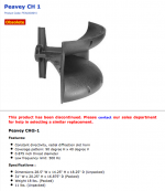
Which Peavey horn are you referring to?
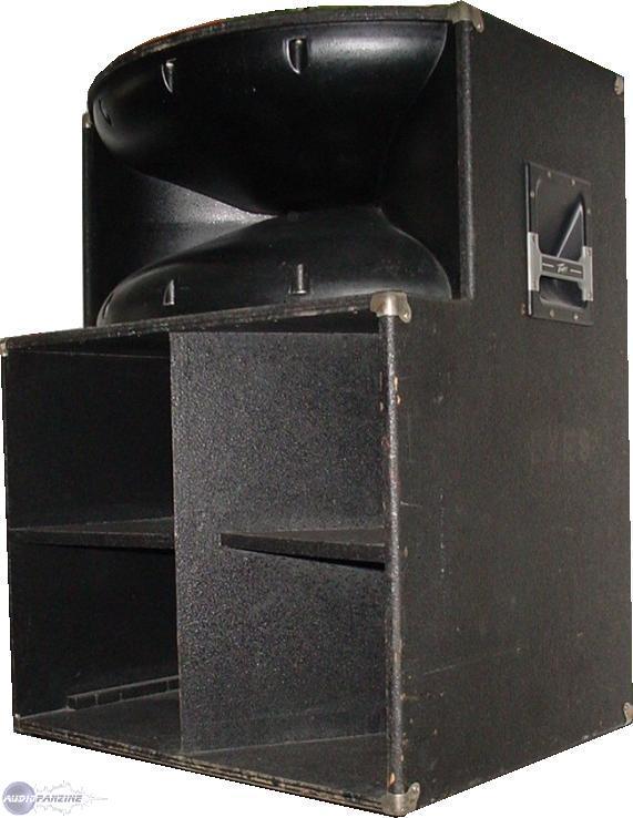
The CH1.Which Peavey horn are you referring to?
The older ones like Pete has used a separate aluminum casting for the diffraction slot throat adapter which was bolted to a fiberglass horn. The newer (also discontinued) version was all injected plastic.
They were used in SP1, SP2, and SP3, though those model numbers were re-used for Peavey products with completely different designs through the decades.
Since this thread is a "guide to Danley tech", note that Danley uses 2 part conical expansion horns which lend themselves to the multiple entrance approach better than a horn like the CH1.
Attachments
Last edited:
Or should I go big...?
Based on my "research" so far and my A$$/2 "calcuations", it looks like to get down to around traditional subwoofer Hz, about 100 Hz, I need a mouth area of just under one meter squared. Do I necessarily gain anything by keeping it in one huge horn? I still am vague on this directionality stuff...many of the smaller horns (nearly all) aim for a low end of anywhere from 200 - 1000 Hz. What is best? Or just design down to the Schroeder frequency (say, 200 Hz)?
Based on my "research" so far and my A$$/2 "calcuations", it looks like to get down to around traditional subwoofer Hz, about 100 Hz, I need a mouth area of just under one meter squared. Do I necessarily gain anything by keeping it in one huge horn? I still am vague on this directionality stuff...many of the smaller horns (nearly all) aim for a low end of anywhere from 200 - 1000 Hz. What is best? Or just design down to the Schroeder frequency (say, 200 Hz)?
Not sure what the Q/'problem' is, but as a general rule, controlling directivity to between ~1000-500 Hz/F6 is sufficient with [original] Unity/Synergy around 1 kHz/90 deg IIRC and Dr. Geddes's Summa around 900 Hz/90 deg to match up to its 15" woofer.
Your 'sub' will therefore be omni minus any room, boundary impact in the XO BW, but for instance you want a 90 deg/F6 pattern down to 200 Hz, then F6 = 10^6/[90*200] = ~55.56" square mouth unless setting on and perpendicular to, a suitably rigid/massive floor, then it can be ~55.56" wide x ~27.78" high.
Size wise, be it one big one or an array, polar response, etc., is normally a trade-off of a number of factors, so only you can make that decision. Personally from using a large corner horn stereo system for much of my life, go as low as you can 'afford' or down to where the room dominates.
GM

Oooh, dat scwoowy crossover!!! Crossover hunt...
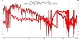
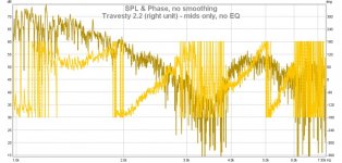
My current Travesty is now more braced and gorilla glued. Fresh towels taped to rear to damp back wave. I ran some REW sweeps around noon today, as best as I can (it's pleasant weather here in FL) with neighbor's circular saw running. Did I also mention I live a few hundred meters from a highway and a regional airport just past that")
I "designed" the Travesty to have ~ 1 KHz crossover. The "lows" or "mids" (as you like, it's a two-way) are now a pair of similar-to-CTS 4C1077 (stock drivers in original Bose 901). All drivers are open to the air (except for damping in rear); Each "mid" has its port, loosely calculated at about 8 cm^2. Distance to tweeter is 8 cm +/- 2 cm. best I could measure.
Head-scratcher: I have tried to find the "crossover" between the mid and high in a speaker (level match each section, invert phase and run a sweep, look for a minimum) but I can't figure out where! Also the 1/2 wave notch of the mid in theory should be 2K-ish but seems more around 3.4 K. Where am I erring? Thanks.
Note these sweeps are just of the mids, no EQ, no delay, etc.
My current Travesty is now more braced and gorilla glued. Fresh towels taped to rear to damp back wave. I ran some REW sweeps around noon today, as best as I can (it's pleasant weather here in FL) with neighbor's circular saw running. Did I also mention I live a few hundred meters from a highway and a regional airport just past that
I "designed" the Travesty to have ~ 1 KHz crossover. The "lows" or "mids" (as you like, it's a two-way) are now a pair of similar-to-CTS 4C1077 (stock drivers in original Bose 901). All drivers are open to the air (except for damping in rear); Each "mid" has its port, loosely calculated at about 8 cm^2. Distance to tweeter is 8 cm +/- 2 cm. best I could measure.
Head-scratcher: I have tried to find the "crossover" between the mid and high in a speaker (level match each section, invert phase and run a sweep, look for a minimum) but I can't figure out where! Also the 1/2 wave notch of the mid in theory should be 2K-ish but seems more around 3.4 K. Where am I erring? Thanks.
Note these sweeps are just of the mids, no EQ, no delay, etc.
Attachments
Might that be the Beeline? In my '50s childhood, I spent many summers at relatives in a locale like you describe; first as a trailer park and later as a nice middle class 'Fla. room' home style subdivision.
Anyway, local noise can wreak havoc on outdoor measurements, so being on a short through street between two major highways with America's busiest private airport within 'spitting distance' and all the planes, news 'choppers', private jets et al and sometimes blimps and/or 'buzz bomb' stunt planes and/or restored WWII prop fighters milling around overhead, I don't 'stand a prayer'.
A cool audio experience though is when a C5A on final approach to Dobbins 'lumbers' over, all the other traffic is ~ drowned out. I've yet to hear any stadium system match it, only moon launches, which I'm guessing would drown out our entire C5 fleet.
Regardless, haven't followed any of your threads in detail or taken time to figure out any of HR's massive updates in the past ~2 yrs, so don't know how to input them even if I had, ergo hope someone who has will chime in.
GM
1) The towels probably have little effect other than reducing high frequencies. If you build some boxes, or find some cups to tape on as chambers you can get a better handle on the response. Some smoothing applied to your tests will also help see the tree within the forest.1)Fresh towels taped to rear to damp back wave.
2)I "designed" the Travesty to have ~ 1 KHz crossover.
3)Head-scratcher: I have tried to find the "crossover" between the mid and high in a speaker (level match each section, invert phase and run a sweep, look for a minimum) but I can't figure out where!
4)Also the 1/2 wave notch of the mid in theory should be 2K-ish but seems more around 3.4 K. Where am I erring?
2) 1 kHz is within the bandwidth of either driver you chose, good.
3) The depth of a reverse polarity null can be used to determine whether the delay is properly set between drivers for a given crossover frequency, or to tell if polarity should be reversed.
Assuming you are inverting polarity between the offset drivers and the driver at the horn apex, both run "full range", the combined response should largely cancel over a wide range, resulting in lower overall level, with peaks and dips scattered though the response.
4)Perhaps you are measuring along the side of the horn, rather than front to back for your theory, along the side is longer.
GM: I dunno the Beeline. I speak of Hernando County airport. My mailing address is Brooksville, or "Brooksvile" as I like to malign it Actually a nice place, despite occasional shot up stop sign or property crime. The county jail is only a 15-minute walk as I've found out at least once
Test outside? Ha ha ha! Maybe at 3 AM but then my neighbors would have me deported
Oh, I should be doing time delay? Duh, ok more testing to follow. I honestly don't know the exact distance of my ports but I aimed for 6 cm (I think) ~ 1000 Hz 1/4 wave. Even if "exact" were possible to me, isn't this measured down the imaginary centerline of the horn | waveguide | rickety structure of coroplast and adhesive
Actually a nice place, despite occasional shot up stop sign or property crime. The county jail is only a 15-minute walk as I've found out at least once Test outside? Ha ha ha! Maybe at 3 AM but then my neighbors would have me deported
Oh, I should be doing time delay? Duh, ok more testing to follow. I honestly don't know the exact distance of my ports but I aimed for 6 cm (I think) ~ 1000 Hz 1/4 wave. Even if "exact" were possible to me, isn't this measured down the imaginary centerline of the horn | waveguide | rickety structure of coroplast and adhesive
- Status
- This old topic is closed. If you want to reopen this topic, contact a moderator using the "Report Post" button.
- Home
- Loudspeakers
- Multi-Way
- Help the Ijit write Ijit's guide to Danley tech