If you're prepared to make drive electronics, then there are much better motors around than the Airpax/Premotec. Take a look at a floppy drive - they have outer rotor three phase motors. I spent yesterday afternoon machining bits of aluminium and steel that will eventually make a smooth running motor out of a pair of 3 1/2" floppy drive motors.
The advantages of floppy drive motors:
Outer rotor means a decent flywheel.
Three phase means less torque ripple compared to two phase.
Designed to be a little more powerful than the Airpax, so can be under-run to avoid saturation.
Better magnetic screening.
The advantages of floppy drive motors:
Outer rotor means a decent flywheel.
Three phase means less torque ripple compared to two phase.
Designed to be a little more powerful than the Airpax, so can be under-run to avoid saturation.
Better magnetic screening.
Sounds very cool. Is there a stand alone 3 phase motor driver? What is being used to drive the 3 phase motor? Is there a slick way to make the 3 phases? Using small power op amps could be the power part. 12 or 5 volts I assume??
As a note, 3 phase motor will start with just the 3 phases. No starting circuit is needed like a 2 phase motor.
As a note, 3 phase motor will start with just the 3 phases. No starting circuit is needed like a 2 phase motor.
I will take some photographs and post them just as soon as I have something sensible. The composite motor will be driven by TDA2030 audio power amplifier ICs (chosen for their extreme cheapness) and the three phases will be generated from a quadrature oscillator as below:
Attachments
I will take some photographs and post them just as soon as I have something sensible. The composite motor will be driven by TDA2030 audio power amplifier ICs (chosen for their extreme cheapness) and the three phases will be generated from a quadrature oscillator as below:
EC,
Thanks for sharing, looking forward to some photos. No rush.
Ron
floppys..have been done before...
have a look at Audio Origami
the complete project should be there. One of the great things about using floppys are that they can be driven by cell phone batteries easily, so a battery powered turntable drive system. I suspect because of the magnetic field about the stationary windings is quite powerful.
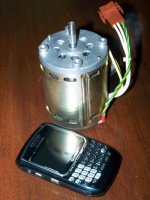
Me thinks an induction motor is the way to go if you yearn for something like a Garrard drive system. Attached is "my choice" for a nice big induction motor. Rated as 23 Watts output, 2850 RPM, 120V, .58A, so about 70 Watts input.
have a look at Audio Origami
the complete project should be there. One of the great things about using floppys are that they can be driven by cell phone batteries easily, so a battery powered turntable drive system. I suspect because of the magnetic field about the stationary windings is quite powerful.
Me thinks an induction motor is the way to go if you yearn for something like a Garrard drive system. Attached is "my choice" for a nice big induction motor. Rated as 23 Watts output, 2850 RPM, 120V, .58A, so about 70 Watts input.
Attachments
Last edited:
further induction motor information...
a few little calculations later and the result is 77.063 mN-m, or about 4X's the torque of the Hurst motors used in many turntables. Not efficient, but very quiet. Only thing is, how do I make it 300 RPM compatible? I guess a suitable 2 step pulley, Output shaft is 7.95 mm in diameter. so it seems that if the motor drives a 75.5mm diameter pulley or idler wheel, then 300 RPM is attainable. From there all that is required is a correct pulley size to allow a 2nd step to drive the platter. Or perhaps just attempt to drive a platter directly if possible")
Running a platter directly from the output shaft: doing a little more math suggests that I would need to drive the motor via 26.896 Hz so that I could just drive the platter (assumed to be 305mm in diameter), to allow for 33 1/3 RPM, and 36.310Hz for 45 rpm
a few little calculations later and the result is 77.063 mN-m, or about 4X's the torque of the Hurst motors used in many turntables. Not efficient, but very quiet. Only thing is, how do I make it 300 RPM compatible? I guess a suitable 2 step pulley, Output shaft is 7.95 mm in diameter. so it seems that if the motor drives a 75.5mm diameter pulley or idler wheel, then 300 RPM is attainable. From there all that is required is a correct pulley size to allow a 2nd step to drive the platter. Or perhaps just attempt to drive a platter directly if possible
Running a platter directly from the output shaft: doing a little more math suggests that I would need to drive the motor via 26.896 Hz so that I could just drive the platter (assumed to be 305mm in diameter), to allow for 33 1/3 RPM, and 36.310Hz for 45 rpm
Last edited:
er..another option to a floppy drive.
see Altmann DIY turntable and tonearm
Charles Altmann does also start comments about a floppy drive motor drive as well
see Altmann DIY turntable and tonearm
Charles Altmann does also start comments about a floppy drive motor drive as well
Yes, the idea of using a floppy drive started with Audio Origami. But he used the motor with its original electronics. He claimed to have been able to adjust the speed with a potentiometer, which seemed unlikely to me since I would expect a crystal controlled phase locked loop. Nevertheless, I took a good look at a floppy drive (yes, it had a crystal PLL), and noted the superior mechanical bits. 5 1/4" drives are beautifully made.
What I found was that 5 1/4" drives typically use a pair of substantial (16 x 8 x 5, and readily available) ball races as their bearings plus a 12 pole motor, whereas 3 1/2" drives use 3.995mm lapped silver steel in phosphor bronze sleeve bearings and a rather smaller 18 pole motor. The big bonus was when I found that the sled carrying the heads in a 5 1/4" drive slid on a 3.995mm lapped silver steel shaft.
The disadvantage of the PLL (for a turntable) is that although it controls the motor to an accurate speed, it doesn't allow speed variation (unless you're prepared to intercept the crystal and add counters etc) and there's lots of torque ripple. Driving the nice motor with sine waves will make for a much smoother rotation and having two motors on one shaft will allow the remaining ripple to be nulled between the two motors.
If you're thinking of pursuing this idea, get your floppy drives now - they're disappearing fast. You're going to need access to a lathe. I will post details...
EC8010
I'm fascinated by your circuit for a quadrature oscillator generating 3 phases, looking at it I have no idea how it works so will have to study it a little longer. I have a couple of CD motors and have been trying to figure out how to generate the 3 phases with adjustable speed control for a couple of weeks now.
The oscillators I've tried so far don't reliably oscillate at the frequency the matches my pulley, and having to change multiple resistors & capacitors at once is frustrating.
Watching this with interest, who know hopefully I may be able to contribute something.
Hi EC8010,
Cool, I am really interested in knowing your method of driving the motor....
Best regards,
Bins.
Cool, I am really interested in knowing your method of driving the motor....
Best regards,
Bins.
Yes, the idea of using a floppy drive started with Audio Origami. But he used the motor with its original electronics. He claimed to have been able to adjust the speed with a potentiometer, which seemed unlikely to me since I would expect a crystal controlled phase locked loop. Nevertheless, I took a good look at a floppy drive (yes, it had a crystal PLL), and noted the superior mechanical bits. 5 1/4" drives are beautifully made.
What I found was that 5 1/4" drives typically use a pair of substantial (16 x 8 x 5, and readily available) ball races as their bearings plus a 12 pole motor, whereas 3 1/2" drives use 3.995mm lapped silver steel in phosphor bronze sleeve bearings and a rather smaller 18 pole motor. The big bonus was when I found that the sled carrying the heads in a 5 1/4" drive slid on a 3.995mm lapped silver steel shaft.
The disadvantage of the PLL (for a turntable) is that although it controls the motor to an accurate speed, it doesn't allow speed variation (unless you're prepared to intercept the crystal and add counters etc) and there's lots of torque ripple. Driving the nice motor with sine waves will make for a much smoother rotation and having two motors on one shaft will allow the remaining ripple to be nulled between the two motors.
If you're thinking of pursuing this idea, get your floppy drives now - they're disappearing fast. You're going to need access to a lathe. I will post details...
I'm fascinated by your circuit for a quadrature oscillator generating 3 phases, looking at it I have no idea how it works...
There are really three parts to the circuit. Starting from the left, the three op-amps form the quadrature oscillator. It's an oscillator because by the time the signal has passed through the two CR networks it has enough phase shift that when it is fed back it increases the voltage. Sustained oscillation is possible because the two 1N4148 diodes clip the feedback signal and prevent the op-amps going to one rail and staying there (saturation).
The oscillator produces sine and cosine, so if you invert each, you get minus sine and minus cosine - which show on the vector diagram as four phases 90 degrees apart. Once you have those four phases, adding proportions of any adjacent two phases will produce any angle between.
Thus, generating the three phases is easier than you might think. Just look at the single op-amp given as the example in the top left. It adds a proportion of sine to a proportion of cosine (90 degrees) to produce the sum at 30 degrees. Use your calculator to verify the arithmetic. Once you can generate 30 degrees, you just have to decide "30 degrees from what?" and repeat the trick to get the other two of the three phases.
Cool, I am really interested in knowing your method of driving the motor....
So am I. I haven't finalised it yet, but TDA2030 will be involved (I bought some).
- Status
- This old topic is closed. If you want to reopen this topic, contact a moderator using the "Report Post" button.
- Home
- Source & Line
- Analogue Source
- Help required for choosing an AC sync motor for a belt driven turntable.