All these alligator clips sound very scary  but it all sounds promising up to now.
What you have to do next is check that the output stages biases up OK and you do that initially with the bulb still in place and NO speakers attached.
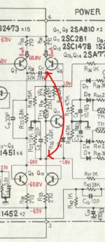
So look at VR2 (thats the bias pot that goes to Q11) and set it to minimum resistance (so its like a short). Unsolder the link wire you put in and switch on and check the bias sets OK (thats the small voltage across the 0.5 ohms). The bulb will glow more as you turn up the bias. That proves its all OK. Turn the bias back down again.
If you want to test with a speaker again then increasing the bias even a tiny amount should remove all the distortion, If it does then I think we test on full mains and set it all up as we did originally.
but it all sounds promising up to now.What you have to do next is check that the output stages biases up OK and you do that initially with the bulb still in place and NO speakers attached.
So look at VR2 (thats the bias pot that goes to Q11) and set it to minimum resistance (so its like a short). Unsolder the link wire you put in and switch on and check the bias sets OK (thats the small voltage across the 0.5 ohms). The bulb will glow more as you turn up the bias. That proves its all OK. Turn the bias back down again.
If you want to test with a speaker again then increasing the bias even a tiny amount should remove all the distortion, If it does then I think we test on full mains and set it all up as we did originally.
I need to feed them regularly or they bite me lol
I removed the short, Bias with trim at min is 0, but when I try to adjust it it goes only negative. I probably inverted the connections (positive pin 13, negative pin 9) since if I measure it on the 0.5 resistor bias will set fine and smooth
Now I will set bias accordingly to the other channel, then I will reassemble the amp and test it
I need to wait until monday for the resistor, in my town I can find only cheap Chinese parts. I will probably use some 2W kiwame
I think the fail is related to the MJE340/350 high temperature, the other predrivers have an heatsink while I didn't use it on the MJE.
Do the MJE340/350 need insulation? I can attach them two aluminum washers and see if it work
I think the fail is related to the MJE340/350 high temperature, the other predrivers have an heatsink while I didn't use it on the MJE.
Do the MJE340/350 need insulation? I can attach them two aluminum washers and see if it work
What happened.... No idea really
I regulated bias to 1mv and offset to zero on both channels, then I removed the alligator connections and reassembled the amp with original connections pin(3-4- 6-7-13-14-IN-E)
Turn on again and it don't work, I checked all connections but I didn't made any mistakes so honestly I don't have a clue
I regulated bias to 1mv and offset to zero on both channels, then I removed the alligator connections and reassembled the amp with original connections pin(3-4- 6-7-13-14-IN-E)
Turn on again and it don't work, I checked all connections but I didn't made any mistakes so honestly I don't have a clue
- Status
- This old topic is closed. If you want to reopen this topic, contact a moderator using the "Report Post" button.
- Home
- Amplifiers
- Solid State
- Help repairing Pioneer M3