Thanks for your help, the resistors are 1 ohm. I measured across them and one resistor measures 46mV across and the other 16mV. I assume that difference is not too bad but does need to be adjusted? If so, which pot applies to that adjustment? Pls see link
https://postimg.org/image/vxvokndoh/
https://postimg.org/image/vxvokndoh/
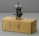
There was another thread on here a few years ago where the guy had exactly the same resistor burn up. I don't remember if it was capacitor failure or toobe failure that caused it. I had a late model FU-29 and the amp is a bargain for the price. Best thing to do is purchase a couple sets of NOS RCA 829 toobes on Epay and replace the driver toobes with Russian stuff. I don't think that is gonna be hard to fix, but you need to find out the value of that resistor...
Mark
Mark
Osvaldo's suggestion is a very good one. (Until you are ready to do the final bias and balance adjustments at which point you must use full mains.)
Also the 46mV/16mV equates to 46mA on one side and 16mA on the other, badly out of adjustment or indicates a bad tube or you've swapped the pair that came with the amp inadvertently. These two values should match closely and should be around 25mV (25mA) - total quiescent current for the entire tube should be around 50mA combined.
Note that any time you change the output tubes you must rebias and rebalance. The correct way is to start with both old tubes installed, decrease the plate current in the first one to be replaced to minimum, shut off the amp and replace JUST that tube. Next turn the amp back on and allow to warm up for a minute, make sure there are no signs of red plating in the new tube. Make the adjustments - do balance first and then increase the plate current. Recheck after a few minutes. Finally repeat the sequence for the other channel, then recheck balance and quiescent current on both channels until things seem stable.
Yes, and also for prevent personal injury or damage.Osvaldo's suggestion is a very good one. (Until you are ready to do the final bias and balance adjustments at which point you must use full mains.)
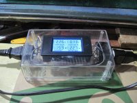
I always use some form of current limiting. I have a box with a lamp of 100W, another for 200 and the third with 300W, and a switch to select one, tho (whichever combination) or the three in parallel (From 100 to 600W), all in series to the live wire in the bench. A completely different outlet color for the "seried" and the direct devices, so, no confusion may be.
First, thanks to all so much for the great advice! As stated before I've worked only on solid state gear... my last valve amp was an Eico ecc83/EL84 way back in the 1970's. Second, to clarify, this Audiromy amp was shipped from Hong Kong without valves. I've fitted my own GE JAN 5670w's and nos RCA 829B's. Next, Prime amp supplied the illustration (link below full size) and based on what I've read here (again thank you) I'm assuming the illustration makes little or no sense...?
https://postimg.org/image/6xu6yocp1/
SO.... in summary. I now understand how to adjust for balance... thank you!
But bottom line... can kevin or other acquainted with the plate bias adjustment please fill me in on doing that? Thanks again so much for helping, steve
")
PS if anyone wishes to re-post the jpeg in the above link as part of a separate post no problem.
https://postimg.org/image/6xu6yocp1/
SO.... in summary. I now understand how to adjust for balance... thank you!
But bottom line... can kevin or other acquainted with the plate bias adjustment please fill me in on doing that? Thanks again so much for helping, steve
PS if anyone wishes to re-post the jpeg in the above link as part of a separate post no problem.
May I suggest to use a current limited supply during tests (For example, using a filament or incandescent lamp in series to the +B or line) at the amp to prevent rectifiers and trafo damaging?
i use this series lamp tester on solid state amps....
tubes can take abuse and you have time to unplug them...
for tubes this is what i use:
Attachments
red plating is the result of over dissipation in the plates,
lowering plate current and or plate voltage cures this...
this is your clue....the object then is to lower plate current
so that the plates do not turn red....
this is what you do with those pots....
having several of the 829b tubes you can select ones that do not red plate,
initially, you can set the grid bias pots to maximum negative voltage,
say -30 volts and the balance pot set to midpoint....
this is how i would do it in my amps...
version board (pls see link)
Kevinkr
Please see link for version board I have... do you know how to adjust the bias on this particular board? I understand about the balance.
https://postimg.org/image/hm1wbm8n5/
thank you
regards,
steve
Osvaldo's suggestion is a very good one. (Until you are ready to do the final bias and balance adjustments at which point you must use full mains.)
Also the 46mV/16mV equates to 46mA on one side and 16mA on the other, badly out of adjustment or indicates a bad tube or you've swapped the pair that came with the amp inadvertently. These two values should match closely and should be around 25mV (25mA) - total quiescent current for the entire tube should be around 50mA combined.
Note that any time you change the output tubes you must rebias and rebalance. The correct way is to start with both old tubes installed, decrease the plate current in the first one to be replaced to minimum, shut off the amp and replace JUST that tube. Next turn the amp back on and allow to warm up for a minute, make sure there are no signs of red plating in the new tube. Make the adjustments - do balance first and then increase the plate current. Recheck after a few minutes. Finally repeat the sequence for the other channel, then recheck balance and quiescent current on both channels until things seem stable.
Kevinkr
Please see link for version board I have... do you know how to adjust the bias on this particular board? I understand about the balance.
https://postimg.org/image/hm1wbm8n5/
thank you
regards,
steve
here you go....
An externally hosted image should be here but it was not working when we last tested it.
You need to identify the pot that sets the bias and the one that controls balance. I would use the series lamp and very carefully adjust the ones on the tube that is red plating on one side.
It would be best if you had two cheap multimeters. (grab a couple on eBay) Bias pot will affect both sides simultaneously and balance will cause one side to increase while the other decreases.
I think the best approach here is to identify the balance pot and adjust so that the voltages are equal, and then adjust the bias.. Keep iterating.
I am not sure why the tubes were not included, the amplifier is set up for a specific pair of output tubes at the factory and needs to be set for each and every pair installed. Your tubes and amp are likely just fine and just badly out of adjustment for the 829 tubes installed.
Your amp by the way is the same as mine. I just don't remember which pot is which. Don't hold to this, but I believe the bias pots are the ones closest to the board edges (right and left) and the innermost are the balance pots - I am not sure so proceed slowly to make sure.
when you use a series lamp tester, the current draw on the power traffo will make the lamp glow and the voltages on the amp itself will be lower, this is the reason i do not use them on tube amps....
except maybe if you use 200 watt of higher incandescent lamps, that will work...
except maybe if you use 200 watt of higher incandescent lamps, that will work...
Check, as AJT indicates a larger wattage lamp is required. Two 100W lamps in parallel with each other and in series with the amp will work and keep it from blowing up while you learn to make adjustments. Once you are comfortable you need to do the final adjustments with full mains.
I use lamps anytime I am repairing on or working on something I don't entirely trust. It has saved some expensive parts over the years.
I use lamps anytime I am repairing on or working on something I don't entirely trust. It has saved some expensive parts over the years.
It's the same test points for both measurements, easiest to do with two meters. You measure the voltage across each resistor.
The pot that adjusts both simultaneously in the same direction is the bias pot.
The one that increases one while decreasing the other is balance.
As I said in a previous post set the balance pot so the voltage read across each 1 ohm resistor is the same.
Then adjust the bias pot so that the voltage read across both resistors simultaneously is 25mVdc.
That's all there is to it. The alternative with a single meter is messier, but you can use one meter to do the comparison between the two halves of the output tube, the technique is the same but requires separate measurements for each and comparison of the values back and forth to get the balance. (The often recommended technique of doing the balance adjustment by measuring across the primary is only OK if the DCR of both winding halves is identical - and it's probably not.)
- Status
- This old topic is closed. If you want to reopen this topic, contact a moderator using the "Report Post" button.
- Home
- Amplifiers
- Tubes / Valves
- Help!!! My Audioromy FU29 amplifier was fried!