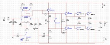
Hello to all community, i have constructed an amplifier, the design is mine. Is bootstraped, BC546 for differential amp, MJE350 for VAS, BC556 for current mirrors, BC546 for BIAS Servo, MJE340-350 for drivers and BD911-912 for output devices.
The usage is for home at 70-80wRMS @ 8ohms and 4ohms some periods,
The rail voltage is 42vDC +/-.
My problem is about quiescent current, i have set it about 25mA per pair (I measure the voltage drop on the pins of the emitter resistors. (about 5.5mV)) but i have a little elevated distortion.
I'm afraid to increase the quiescent current because last month i've blow up all output devices from too much quiescent current.
The circuit is working, but i would appreciate the appreciation and your help in case of error.
Thanks for all, Happy holidays and merry christmas!
Attachments
It looks like a pretty reasonable design (just as a quick look-see).
I'm a bit concerned about stability given the lack of the damped L at the output. It would probably measure fine, but a real speaker might make it oscillate. That could have even been a contributing factor to the failure you mentioned.
Is the Vbe multiplier attached to the heatsinks for the output devices? That can be useful to have thermal feedback to help bias stability.
Update My Dynaco
Akitika GT-101 Audio Power Amplifier Kit
It looks like a pretty reasonable design (just as a quick look-see).
Thank you very much!!
I'm a bit concerned about stability given the lack of the damped L at the output. It would probably measure fine, but a real speaker might make it oscillate. That could have even been a contributing factor to the failure you mentioned.
maybe, i dont know right now.... But it have good sound quality!
Is the Vbe multiplier attached to the heatsinks for the output devices? That can be useful to have thermal feedback to help bias stability.
yes, the vbe is attached to main heatsink with cables...
Update My Dynaco
Akitika GT-101 Audio Power Amplifier Kit
")
reduce the value of R21, try to increase your quescent current and see if it works.
in multisim, seems to work better, with 100R from 220, i do some tests today in real life!
reducing the value of R21 reduces idle current more....
you are running close to class B, running it class AB will help a bit.
make R11 higher, say 2.2k and try again...
go for at least 50mA per pair....
I will test it with TIP30550/2955 today for output devices....
My opinion was 50-60mA per pair, just wanted to make sure for this...
I'm a hobbyist and always need help if I'm not sure at what I do.
results will have the evening, stay tuned!!
Set the output bias by voltage (Vre), not current.
The voltage across the output device emitter resistors should be around 26mVre.
But this Voltage includes the transistor's internal voltage drop across it's intrinsic emitter resistance (to any AC guru: Is that a correct way to explain this?)
As the external emitter resistance is lowered the proportion of the total emitter resistance is increased in the internal side and reduced in the external side.
At 0r22, one is starting to see a reduction in Vre. Try for maybe around 20mVre to 22mVre.
At 0r1 many are finding that 18.5Vre is best for lowest crossover distortion.
Whereas for 0r47 usually 25mVre to 26mVre is good.
The bias currents (quiescent current when zero signal is present) are usually set by applying a fixed voltage across pre-set resistance.
R9 sets bias for Q1, 2, 3, & 4.
R13+14 for Q6.
R21 for 8 & 9.
R12:R11 for Q10, 11, 12, & 13.
(note that Vr13+14 is NOT a fixed voltage: it depends massively on how the supply rail voltage changes during amplifying operation)
Check the currents in all the transistors and see where they lie on the hFE vs Ic curve and on the fT vs Ic curve. If you are way off to one side of the Ic values given in the datasheet curves, then your transistors will not perform as well. And performance begins to depend on which transistor operates least well. i.e. the transistor parameter begins to determine the amplifier performance, (not good).
Last edited:
reducing the value of R21 reduces idle current more....
you are running close to class B, running it class AB will help a bit.
make R11 higher, say 2.2k and try again...
go for at least 50mA per pair....
then your making it too risky..
increasing vas will result to high Voltage and current across 220R.
one way is to compensate the the VAS current without increasing the voltage across R21.
lets say you have 1V across 220R, then I=(1/220r) = 4.5mA
then if you reduce to 100R at same current,you would probably get 0.45V. Increase your VAS current until it reaches 1V across 100R and you will have 10mA.
You do not show any decoupling capacitors on any of the supply rails !
This omission can create terrible distortions and terrible oscillations.
in simulation he did not add decoupling since the source is pure dc. but in reality it must be added as what you had said the effects.
I would add a base resistor to Q6 -2x its max base curent(0.5w carbon film),and remove c3.Then for Q8 ad a 25pf capacitor from Base to Emitter to minimize distortions by reducing amplified bandwith.
C6 should be 470nF-680nF,and i would use 1nF + 91pf SilverMica cap for Q4.About the input filtering its all wrong,you need 1st: RC HP -cap at least 4uF and 2nd: RC LP -resistor 2w 5-10ohm <5uH wirewound or metal film.
Before the first filter 100k resistor to ground.
Use BC560 BC550 much better transistors.
Last edited:
Set the output bias by voltage (Vre), not current.
The voltage across the output device emitter resistors should be around 26mVre.
But this Voltage includes the transistor's internal voltage drop across it's intrinsic emitter resistance (to any AC guru: Is that a correct way to explain this?)
As the external emitter resistance is lowered the proportion of the total emitter resistance is increased in the internal side and reduced in the external side.
At 0r22, one is starting to see a reduction in Vre. Try for maybe around 20mVre to 22mVre.
At 0r1 many are finding that 18.5Vre is best for lowest crossover distortion.
Whereas for 0r47 usually 25mVre to 26mVre is good.
The bias currents (quiescent current when zero signal is present) are usually set by applying a fixed voltage across pre-set resistance.
R9 sets bias for Q1, 2, 3, & 4.
R13+14 for Q6.
R21 for 8 & 9.
R12:R11 for Q10, 11, 12, & 13.
(note that Vr13+14 is NOT a fixed voltage: it depends massively on how the supply rail voltage changes during amplifying operation)
Check the currents in all the transistors and see where they lie on the hFE vs Ic curve and on the fT vs Ic curve. If you are way off to one side of the Ic values given in the datasheet curves, then your transistors will not perform as well. And performance begins to depend on which transistor operates least well. i.e. the transistor parameter begins to determine the amplifier performance, (not good).
very illustrative, and not for something I was not sure as to my measurements now i'm sure
You do not show any decoupling capacitors on any of the supply rails !
This omission can create terrible distortions and terrible oscillations.
Multisim have pure DC, in real life i have 2200uF / 100nF and 1MΩ resistor per rail. Resistors is for discharging power supply capacitors.
You show C5 connected to the Power Ground.
You also show R2 and C2 connected to Power Ground.
All three components must connect to Signal Return/Ground.
Maybe that is my big mistake about distortion, now i'm printing the new PCB. I found some more errors to old PCB...
Is correct to apply a 10R resistor from power ground to signal ground?
What voltage drop do you have across LED1 as this sets up the current source value . If its 1.8V this would give approx 1.2V across R9 and make the source current 5.45mA and thus the voltage drop across R8 54V .
i have 1.78V across led1
Led is standard 1mm green led....
in simulation he did not add decoupling since the source is pure dc. but in reality it must be added as what you had said the effects.
I would add a base resistor to Q6 -2x its max base curent(0.5w carbon film),and remove c3.Then for Q8 ad a 25pf capacitor from Base to Emitter to minimize distortions by reducing amplified bandwith.
C6 should be 470nF-680nF,and i would use 1nF + 91pf SilverMica cap for Q4.About the input filtering its all wrong,you need 1st: RC HP -cap at least 4uF and 2nd: RC LP -resistor 2w 5-10ohm <5uH wirewound or metal film.
Before the first filter 100k resistor to ground.
Use BC560 BC550 much better transistors.
Thank you! i will test it to breadboard and i tell you the results!
i have 1.78V across led1
Led is standard 1mm green led....
Then the current source value is trying to be approx 5.22mA but is being stiffled by the 10kohm of R8 (.00522 x 10k = 52.2V ) so reduce R8 to 3.9kohm (.00522 x 3.9k = 20.35V ) , result ... the remaining negative rail volts will be shared by R8 and Q5 and allow the current source to work .
Last edited:
Originally Posted by AndrewT:
You show C5 connected to the Power Ground.
You also show R2 and C2 connected to Power Ground.
All three components must connect to Signal Return/Ground.
most amplifiers/opamps/pre-amps require a "reference" between the input and output to set the correct voltages as they pass through...................Maybe that is my big mistake about distortion, now i'm printing the new PCB. I found some more errors to old PCB...
Is correct to apply a 10R resistor from power ground to signal ground?...............
A connection from Signal Return to Speaker/output Ground/Return is required for this "reference".
If there is no interference current flowing, then a direct wire connection is good for this reference connection.
BUT, any two channel, or multi-channel, amplifier generally has a loop picking up interference if both Signal Returns connect to the commoned Output Returns.
A partial cure for this loop interference is a current reducing resistance in the loop.
You MUST UNDERSTAND why this happens and why it attenuates, to be able to locate the added resistance correctly for your multi-channel amplifier.
Read D.Joffe.
Single channel amplifiers do not suffer from this loop interference problem.
The voltage across the output device emitter resistors should be around 26mVre.
ok, 26mv/0.22ohms = 118mA, is your heatsink big enough to handle 5 watts per trannie of collector dissipation?
i have 1.78V across led1
Led is standard 1mm green led....
Then the current source value is trying to be approx 5.22mA but is being stiffled by the 10kohm of R8 (.00522 x 10k = 52.2V ) so reduce R8 to 3.9kohm (.00522 x 3.9k = 20.35V ) , result ... the remaining negative rail volts will be shared by R8 and Q5 and allow the current source to work .
something still not add up...assuming we have a tail current of 5.22ma shared by the ltp pair, then (5.22/2)x220ohm = 574mV across the 220ohm R3, add to this is 0.6 volts, for a total of 1.174 volts appearing at the base emitter of Q6, certainly this is not right...
something is wrong somewhere.....it is then a miracle that output offset voltage is not huge....
I am not sure what you are describing.I would add a base resistor to Q6 -2x its max base curent(0.5w carbon film),and remove c3.Then for Q8 ad a 25pf capacitor from Base to Emitter to minimize distortions by reducing amplified bandwith.
C6 should be 470nF-680nF,and i would use 1nF + 91pf SilverMica cap for Q4.About the input filtering its all wrong,you need 1st: RC HP -cap at least 4uF and 2nd: RC LP -resistor 2w 5-10ohm <5uH wirewound or metal film.
Before the first filter 100k resistor to ground.
Use BC560 BC550 much better transistors.
"Q6 -2x its max base curent" What does this mean?
"remove c3.Then for Q8 ad a 25pf capacitor from Base to Emitter to minimize distortions by reducing amplified bandwith." does all this need to be read as ONE instruction? or are they two different and unrelated advice topics?
"C6 should be 470nF-680nF,and i would use 1nF + 91pf SilverMica cap for Q4"
Again is this one suggestions or two different advices on different topics?
"2nd: RC LP -resistor 2w 5-10ohm <5uH wirewound or metal film." What is this for? why 5-10ohm? why <5uH? why wirewound? why 2W?
in simulation he did not add decoupling since the source is pure dc. but in reality it must be added as what you had said the effects.
huh?
- Status
- This old topic is closed. If you want to reopen this topic, contact a moderator using the "Report Post" button.
- Home
- Amplifiers
- Solid State
- Help for quiescent current adjustment