And today, this is the dismatled Conrad Johnson DF1 face-plate :
- just behind face-plate with its Philips controls & display card :
- and the reverse side :
I have to verify all that.
Raymond
- just behind face-plate with its Philips controls & display card :
An externally hosted image should be here but it was not working when we last tested it.
- and the reverse side :
An externally hosted image should be here but it was not working when we last tested it.
I have to verify all that.
Raymond
You have it all in bits then... I was looking at the motor circuit, and see it uses a Hall effect sensor for rotational info and feedback. There is also a pot on the motor PCB to optimise the "drive waveform"... the motor is AC.
I think the real test is just to see if it still rotates when the VC line is grounded.
I think the real test is just to see if it still rotates when the VC line is grounded.
... ... I think the real test is just to see if it still rotates when the VC line is grounded.
You are right, but I have some problem to find VC line on diagram !!!
For it, I have to reset all that now.
Raymond
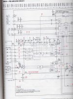
... ... The VC line is from the output of the final opamp in the last diagram I posted... one of the four leads to the motor. Just apply a short across collector and emmiter of that transistor that mutes that line and see if it kills the motor rotation.
Yes it kills !
But nothing appear from pin n°21.
And your diagram is wholly different.
Incomprehensible.
I will put this CD/preamp in a corner, take some time to think, and wait to find two MAB8441 for buying ( Dönberg Electronics promises me ? )
Raymond
ps : perhaps more difficult than my work on LEVINSON ML-2 !!!
Why is it different ?
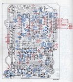
This is the underside view of the PCB in your photo.
If shorting the VC line kills the motor then the same should be true if pin 21 is low... and you say it is "nothing on pin 21" so the fault has to be in the mute circuit as I described.
So you need to recheck/confirm... pin 21 low.
Do you see those three diodes... D6110, 6111, 6116 that have there anodes connected together. There should be 5 volts on the anodes if pin 21 is low. If so that then turns on the mute transistors killing the VC line by shorting it to ground via the transistors... maybe one of the diodes or transistors is OC.
if not and no 5 volts on those anodes, then the logic invertor transistor is OC
Attachments
Last edited:
Why is it different ?
This is the underside view of the PCB in your photo.
If shorting the VC line kills the motor then the same should be true if pin 21 is low... and you say it is "nothing on pin 21" so the fault has to be in the mute circuit as I described.
So you need to recheck/confirm... pin 21 low.
Do you see those three diodes... D6110, 6111, 6116 that have there anodes connected together. There should be 5 volts on the anodes if pin 21 is low. If so that then turns on the mute transistors killing the VC line by shorting it to ground via the transistors... maybe one of the diodes or transistors is OC.
if not and no 5 volts on those anodes, then the logic invertor transistor is OC
Hello Mooly,
I do what you said me :
- pin 21 ( IC6101) is as previous, either +5volts, or 0volt
- but after...
- and if I put VC = 0volt, CD motor stops
See below I make all these voltage measurements :
An externally hosted image should be here but it was not working when we last tested it.
What do you think now ?
The best would be to change Q6106 ( BC858B ) but not sure
About this servo card, I have no diagram ( your layout was a good thing for me !! ) for my understanding
Thanks to You again,
Raymond
Q6106 appears faulty. I can't see there being any "contributing" cause as it's all high impedance stuff off the collector.
As a further test, if you apply a short across C and E of Q6016 the motor should stop.
You can use an "ordinary" transistor if you can make it fit, something like a BC556 etc... just watch the pinouts.
Just to go back to the readings, and the voltage on points B and D. D is fixed at 5 volts. point B can never go lower than around 4.3 volts due to the Base Emmiter volt drop of the transistor. So you having 2.9 volts on there is a sure guide it's duff.
Q6106 appears faulty...
YES !!
It seems out ( with my cheap multimeter on diode position ).
But I dare not believe it is the whole responsible of this trouble.
And You, Mooly, are better than Sherlock Holmes.
Thanks again,
Raymond
ps : I have some difficulty to read the diagram : do you confirm Q6106 = BC858b ?
Lol... it is a BC858b. Anything at all (PNP of course) with a reasonably high hfe (gain) should be fine.
And believe it !! Well fix it first, and then believe")
Faults like this are common... it's never ever ever the IC's or Microprocessors.
If you are ever unsure, you go around every pin and check that what you see is what you expect... supplies, reset pulse, inputs... and it's always something external to the chip 99 time out of 100.
And believe it !! Well fix it first, and then believe
Faults like this are common... it's never ever ever the IC's or Microprocessors.
If you are ever unsure, you go around every pin and check that what you see is what you expect... supplies, reset pulse, inputs... and it's always something external to the chip 99 time out of 100.
Fixed by morning then ?
just be careful not to zap anything... those Philips solid core wires are fragile that go to all the plugs.
I must buy this BC858 at Electronique Diffusion ( 10 miles from my home ).
It will be the second time I shall solder a SMD ( the first time it was a led chip and I spent half an hour to rediscover it on my floor and in addition I had to find the right direction ).
Raymond
Better buy a couple then
just in case lol
http://www.diyaudio.com/forums/parts/127924-working-smd-how-do-without-specialised-tools.html
just in case lol
http://www.diyaudio.com/forums/parts/127924-working-smd-how-do-without-specialised-tools.html
Better buy a couple then
just in case lol
http://www.diyaudio.com/forums/parts/127924-working-smd-how-do-without-specialised-tools.html
Fine work Mooly !!
For this Q, I will have only 3 legs to unsolder.
Please, have you schematic diagram for this servo card ( servo + HF amp circuit ) ?
There is nothing about it on my CD350 service manual.
Nice day for You,
Raymond
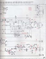
You mean this,
You are truly THE BEST !!
Thanks again
I am taking my shoes for going tu buy these BC858
Raymond
Good luck with it... post how you get on.
- BC558 SMD soldered
- CDM-4 fitted in
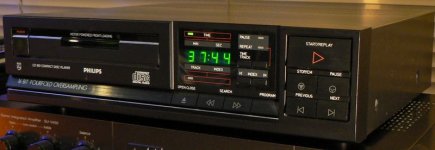
- and my Conrad Johnson DF1 plays perfect now !!
Marvellous Mooly.
- The only bad thing surviving - before it was - is one problem with led display on the faceplate :
See the number " 5 " with its median bar missing ( also for 2, 3, 4, 6, 8 and 9 ).
An externally hosted image should be here but it was not working when we last tested it.
One idea Mooly ?
You know all the responses.
I would think this is a failure in the led display block and then nothing better to do.
Raymond
That's great that it all works... a bit of classic faultfinding
The display itself is faulty, it was a common problem on the Philips machines.
You really don't want to read this, I had one and sent it to another DIY member down under. Post #13,
http://www.diyaudio.com/forums/digital-line-level/101748-lcd-readout-broken-bad-joints.html
So you must keep a lookout for old scrap Philips players... don't know if they would still be available new as a spares item and if they were at what cost.
Really pleased you have fixed the main fault though.
- BC558 SMD soldered
- CDM-4 fitted in
- and my Conrad Johnson DF1 plays perfect now !!
Marvellous Mooly.
- The only bad thing surviving - before it was - is one problem with led display on the faceplate :
See the number " 5 " with its median bar missing ( also for 2, 3, 4, 6, 8 and 9 ).
An externally hosted image should be here but it was not working when we last tested it.
One idea Mooly ?
You know all the responses.
I would think this is a failure in the led display block and then nothing better to do.
Raymond
First congratulation to your troubleshooting and error remove. This failing I would not have believed as the most likely cause.
Unfortunately the display driver IC and the seven segment displays here is one module (one unit):
Type NSM4202A Philips code: 4822 130 90262
used e.g. by cheap to get Philips "CD-160" (CD160), additional by CD-350 and some other models (in this aera industry standart, not custom made device, available in green, yellow and red - as I know)
here some other links, perhaps useful:
http://www.diyaudio.com/forums/parts/152991-anyone-know-source-nsm4202a-led-board.html
Re: Assistance with obsolete parts
philips cd 160 display, Suche - HIFI-FORUM
http://www.okdatasheet.com/datasheets/ATMEL/NSM4202A.html
An other possibility it could be to find out the IC type of the internal display driver IC. Then you can buy this and 4 pieces of 7 segment displays to clone this. The advantage is here to get a part in a new condition, the disadvantage the great effort.
Attachments
Last edited:
- Status
- This old topic is closed. If you want to reopen this topic, contact a moderator using the "Report Post" button.
- Home
- Source & Line
- Digital Source
- Help! CONRAD JOHNSON DF1 CDplayer-preamp