Hi. I think I did.... ;-)
I am struggling with inserting the transformer. I keep getting an error message saying I need to add series resistance. (I'm away from my Mac and so don't have the full warning/error message to hand.) I spent several hours on it until the wee hours of the morning last night and had to walk away frustrated in the end. And that was attempting to model a simple transformer with just one primary and one secondary let alone modelling the dual primaries/secondaries.
I also seem to have a problem at or post the regulator as the "probed" voltages there don't make sense.
I'm surprised the asc file isn't readily transferable from a Mac to Windows. I had no problems opening the file you posted and it all looks normal on the Mac.
Re posting the .asc file, I originally uploaded it to the forum but the advantage of posting a Dropbox link is that I can update the file without having to upload it again.
While this is a steep and somewhat frustrating learning curve - this little power supply rail is rather basic - I can already appreciate how helpful LTSPICE is.
That's very kind. The version linked to doesn't have a transformer included. I saved a different version while I was still getting the error. But the load part is there.
My understanding is that I need to model 4 inductors (2 primary and two secondary) wire them as they would be physically wired, input a mutual inductance statement (for now setting them all to 1 – can a more accurate number be derived from the data sheet e.g. transformer efficiency?) and input the inductance values in H for each inductor. I suspect this last part is where I am going wrong. I have two primary rated 115V and two secondary rated 15V. I understand the voltage ratio is proportionate to the windings ratio and inductance is the square of the windings. So if I am not mistaken that’s 115^2 : 15^2 = 529:9. I'm not sure if the decimal place is relevant here, i.e.u, m or whatever, or merely the ratio between the two numbers.
My understanding is that I need to model 4 inductors (2 primary and two secondary) wire them as they would be physically wired, input a mutual inductance statement (for now setting them all to 1 – can a more accurate number be derived from the data sheet e.g. transformer efficiency?) and input the inductance values in H for each inductor. I suspect this last part is where I am going wrong. I have two primary rated 115V and two secondary rated 15V. I understand the voltage ratio is proportionate to the windings ratio and inductance is the square of the windings. So if I am not mistaken that’s 115^2 : 15^2 = 529:9. I'm not sure if the decimal place is relevant here, i.e.u, m or whatever, or merely the ratio between the two numbers.
:
 . I just used the windows version wrapped in a wineskin emulator. Works fine, but cool Mac is finally being acknowledged. I've downloaded the 12-11-'13 version and see it looks rather different, but all tools are there. They're just under the right mouse button instead of the toolbar. You'll be better of remembering the speedkeys anyway. Works way faster.
One annoying thing is the inability of the file to detect libs in sub directories of the .asc file.
For certain types of components, like e.g. a simple LM317 or UF type diode etc, you have to find the spice model online somewhere. Spice comes with its own syntax in which the specific characteristics of a component are described for simulation purposes (to great detail!). This 'model' can then be coupled to the components already present in the schematic. It might take a bit of googling though. Lots of models (or links to them) on this forum as well.
I didn't know there was a native Mac version!Thanks Mooly
Funk1980, have you tried using the Mac version that was released in August?
I'm making some progress with LTSPICE for Mac but it is a little like poking around in the dark - both because of my limited knowledge of electronics and limited knowledge of SPICE. The Mac version doesn't have the toolbars but it seems to all be there. It seems that the equivalent of "Edit Simulation Command" in Windows is just a text editor requiring one to know how the commands/fields end up in the text string.
I've linked to the (very basic) asc file I have so far. I can't figure out a few things, namely:
- the circuit presumably needs some sort of load or Vout representation after C3 (EDIT: I think I have fixed this?)
- I just picked a generic Schottky diode for the bridge diodes. I can't see how to refine this for the Cree diodes I have.
- same thing for the regulator. I don't have the information to model the Fidelity Audio SPower HC regulator (+12V, circa 5V drop)
- I'm not getting the AC voltage I was expecting to measure (15V) nor the level of DC after rectification (I was expecting circa 15 x 1.4 - 2 = 19V)
etc etc
Until I get these basics right it's hard to move forward. I will keep at it.
. I just used the windows version wrapped in a wineskin emulator. Works fine, but cool Mac is finally being acknowledged. I've downloaded the 12-11-'13 version and see it looks rather different, but all tools are there. They're just under the right mouse button instead of the toolbar. You'll be better of remembering the speedkeys anyway. Works way faster.One annoying thing is the inability of the file to detect libs in sub directories of the .asc file.
For certain types of components, like e.g. a simple LM317 or UF type diode etc, you have to find the spice model online somewhere. Spice comes with its own syntax in which the specific characteristics of a component are described for simulation purposes (to great detail!). This 'model' can then be coupled to the components already present in the schematic. It might take a bit of googling though. Lots of models (or links to them) on this forum as well.
One annoying thing is the inability of the file to detect libs in sub directories of the .asc file.
I wonder if this explains the weird results I'm getting when probing voltage at nodes after the regulator I dropped in?
BTW am I on sound footing (excuse the pun) re the below for transformer wiring?
What's good practice for the dealing with the wires that need to be jumpered? I presume one cuts them short, solders them and insulates with heatshrink sleeving but want to check. Lastly, if the long primary leads aren't quite long enough to reach the IEC inlet, again, what's best practice? I assume it is best to run a length of good quality, shielded power cable through the enclosure and again cut the existing primary leads short, solder and shield with heatshrink?
Sorry for the basic questions but given this is the first time I am doing this and AC is involved I want to make sure I am doing everything safely.
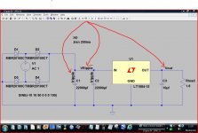
Here we go. With simulation you have to be creative sometimes. This was my best guess for setting it up. I've put the E.S.R. of the main caps at 0.04ohm. The output cap should probably not be to large. When I ran the sim the reg didn't seem to support 1.1 ohms so you can try different values for Rload.
Modeling a transformer... I'll be honest I haven't a clue there.
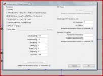
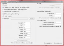
I mentioned being creative. A dynamic load is revealing. Use a power MOSFET across the output with a suitable load in series (Rload) and drive the FET from another voltage source on the gate (such as a pulsed 100Hz or pulsed 10kHz etc). You can model a DC rail with ripple easily to, you don't need the bridge and caps to do that. See the picture of settings for a 45 volt rail with ripple.
Modeling a transformer... I'll be honest I haven't a clue there.
I mentioned being creative. A dynamic load is revealing. Use a power MOSFET across the output with a suitable load in series (Rload) and drive the FET from another voltage source on the gate (such as a pulsed 100Hz or pulsed 10kHz etc). You can model a DC rail with ripple easily to, you don't need the bridge and caps to do that. See the picture of settings for a 45 volt rail with ripple.
Attachments
BTW am I on sound footing (excuse the pun) re the below for transformer wiring?
Lots of different approaches really. Heatshink is fine if applied properly. I woudn't go chopping the primary leads to short... you might regret it later if you want to reuse the tranny in something else.
I wonder if this explains the weird results I'm getting when probing voltage at nodes after the regulator I dropped in?
No, LTSpice will let you know specificly it can't find the .lib file.
Last edited:
I see you have gone to the expense of buying Bob Cordell's book, and made some effort into the bargain.
IMO modelling a txfrmr in LTspice is not a useful exercise at your stage of learning. A txfrmr model is very useful if you are interested in simulating a tube amp, but PSUs can be designed adequately without resorting to simulation.
You will get a much better grasp of how to design a linear PSU if you buy or borrow a copy of 'The Art of Electronics' by Paul Horowitz and Winfield Hill, which you will also find useful in many other areas. It is widely regarded as probably the best introduction to general electronic design available, and it will fill in many of the inevitable lacunae in your knowledge.
I spent some time with LTspice. Here is a link to the LTspice simulation circuit material.
Here are a few screenshots:
Circuit
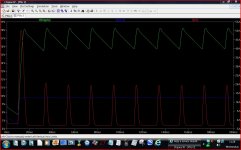
Current on primary
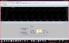
Current on secondaries
Voltages into the regulator (I just used a basic LT1084-12 as I can't model the advanced SPower)
A closer look at the output voltage
The very plain spoken conclusion from those on the LTspice Yahoo Group that gave me some help setting up the transformer in the LTspice simulation was "you do not need a snubber" and, with respect to the film caps and choke, "no, they will do nothing useful". I didn't get as far as understanding how to use LTspice to look for transistormarkj's predictions.
Here are a few screenshots:
Circuit
An externally hosted image should be here but it was not working when we last tested it.
Current on primary
An externally hosted image should be here but it was not working when we last tested it.
Current on secondaries
An externally hosted image should be here but it was not working when we last tested it.
Voltages into the regulator (I just used a basic LT1084-12 as I can't model the advanced SPower)
An externally hosted image should be here but it was not working when we last tested it.
A closer look at the output voltage
An externally hosted image should be here but it was not working when we last tested it.
The very plain spoken conclusion from those on the LTspice Yahoo Group that gave me some help setting up the transformer in the LTspice simulation was "you do not need a snubber" and, with respect to the film caps and choke, "no, they will do nothing useful". I didn't get as far as understanding how to use LTspice to look for transistormarkj's predictions.
Transformer snubbers counteract the oscillatory ringing caused by nonzero transformer secondary leakage inductance. Your LTSPICE simulations won't include secondary leakage inductance (nor its oscillatory ringing) unless either (a) you measure the transformer coupling ratio and simulate the measured value (hint: you will measure K < 1.000000); or else (b) you measure the actual secondary leakage inductance and include it as an explicit unlinked inductance in series with the "ideal (K=1.000000)" transformer secondary (hint: Lleakage > 0.000000). The simulations you showed in post # 33 have assumed K = 1.000000 and Lleakage = 0.000000.
I suggest you measure an actual transformer using actual test equipment in your own actual hands. Bellringer test-jigs like Quasimodo are only one way to do so (but I.M.H.O. they are the easiest way to do so); try whatever measurement technique you like, and see whether or not you measure K = 1.000000, or Lleakage = 0.000000. Why take somebody else's word (opinion) when you can perform experiments yourself and reason to conclusions yourself?
I suggest you measure an actual transformer using actual test equipment in your own actual hands. Bellringer test-jigs like Quasimodo are only one way to do so (but I.M.H.O. they are the easiest way to do so); try whatever measurement technique you like, and see whether or not you measure K = 1.000000, or Lleakage = 0.000000. Why take somebody else's word (opinion) when you can perform experiments yourself and reason to conclusions yourself?
Yes I am talking about snubbers for "transformer ring" a la Quasimodo.
On the LTspice model, there's a few things I can tidy up. The question is what to do with it. ;-)
OK
You see, I tend look at this from practical experience (as a repair tech) and know for a fact that some commercial equipment has problems due to not having snubbers. On that basis alone, the problem is real. You can try and analyse all the details but the simple fact is that as the rectifiers come out of conduction strange things can happen. Ringing, bursts of RF and so on. One such case was a small AM/FM mains battery radio. On mains it had a harsh 50 Hz buzz on FM. Am was fine. The cure was to add a 0.01uf cap across the secondary. Another was an upmarket Hitachi tuner, It buzzed on the audio. Same issue again. The rectifiers needed snubbing.
So yes, its a real problem but I wouldn't sweat the details in simulation. A proper C/R snubber 100% takes the problem away.
The simulation was a bit of a detour. I don't regret it because I learnt a few things along the way but it's clear I need to get this thing up and running and measure it. For that I await a couple of parts (IEC inlet and circuit breaker - at least on this last one the sim suggests 2A is likely too low). Thanks for the help guys.
Mark, while I read your paper and wait for parts and access to an oscilloscope, how might I simulate the ringing in LTspice? Set K slightly less than 1 but how to observe the plots you posted in the Quasimodo thread? Is this possible?
PS: Is it your view that the Pi filter is a waste of time?
PS: Is it your view that the Pi filter is a waste of time?
- Status
- This old topic is closed. If you want to reopen this topic, contact a moderator using the "Report Post" button.
- Home
- Amplifiers
- Power Supplies
- Help a novice steadily build a linear 12V power supply?